Infiniti FX35 / FX45. Manual — part 444
DTC P2A00, P2A03 A/F SENSOR 1
EC-537
< SERVICE INFORMATION >
[VQ35DE]
C
D
E
F
G
H
I
J
K
L
M
A
EC
N
P
O
: Average voltage for pulse signal (Actual pulse signal can be confirmed by oscilloscope.)
Diagnosis Procedure
INFOID:0000000001326424
1.
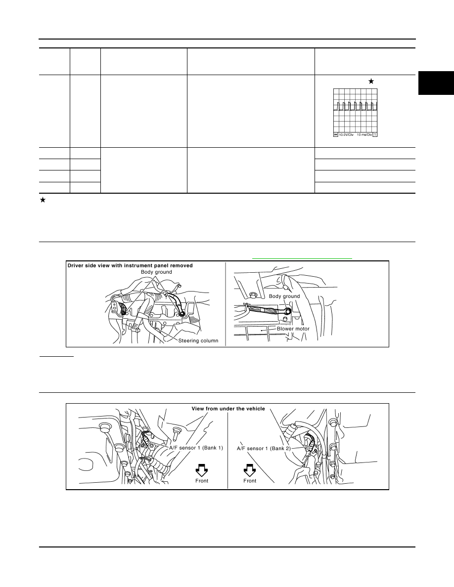
CHECK GROUND CONNECTIONS
1.
Turn ignition switch OFF.
2.
Loosen and retighten ground screw on the body. Refer to
OK or NG
OK
>> GO TO 2.
NG
>> Repair or replace ground connections.
2.
RETIGHTEN AIR FUEL RATIO (A/F) SENSOR 1
Loosen and retighten the air fuel ratio (A/F) sensor 1.
>> GO TO 3.
3.
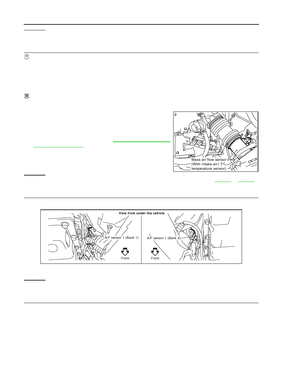
CHECK FOR INTAKE AIR LEAK
1.
Start engine and run it at idle.
2.
Listen for an intake air leak after the mass air flow sensor.
TERMI-
NAL
NO.
WIRE
COLOR
ITEM
CONDITION
DATA (DC Voltage)
24
L
A/F sensor 1 heater
(bank 2)
[Engine is running]
• Warm-up condition
• Idle speed
Approximately 5V
57
G
A/F sensor 1 (bank 2)
[Engine is running]
• Warm-up condition
• Idle speed
Approximately 2.6V
58
Y
Approximately 2.3V
76
P
Approximately 3.1V
77
BR
Approximately 2.3V
PBIB1584E
PBIB2625E
Tightening torque: 40 - 60 N-m (4.1 - 6.1 kg-m, 30 - 44 ft-lb)
PBIB2200E
EC-538
< SERVICE INFORMATION >
[VQ35DE]
DTC P2A00, P2A03 A/F SENSOR 1
OK or NG
OK
>> GO TO 4.
NG
>> Repair or replace.
4.
CLEAR THE SELF-LEARNING DATA
With CONSULT-III
1.
Start engine and warm it up to normal operating temperature.
2.
Select “SELF-LEARNING CONT” in “WORK SUPPORT” mode with CONSULT-III.
3.
Clear the self-learning control coefficient by touching “CLEAR”.
4.
Run engine for at least 10 minutes at idle speed.
Is the 1st trip DTC P0171, P0172, P0174 or P0175 detected?
Is it difficult to start engine?
Without CONSULT-III
1.
Start engine and warm it up to normal operating temperature.
2.
Turn ignition switch OFF.
3.
Disconnect mass air flow sensor harness connector.
4.
Restart engine and let it idle for at least 5 seconds.
5.
Stop engine and reconnect mass air flow sensor harness con-
nector.
6.
Make sure DTC P0102 is displayed.
7.
Erase the DTC memory. Refer to
8.
Make sure DTC P0000 is displayed.
9.
Run engine for at least 10 minutes at idle speed.
Is the 1st trip DTC P0171, P0172, P0174 or P0175 detected?
Is it difficult to start engine?
Yes or No
Yes
>> Perform trouble diagnosis for DTC P0171, P0174 or P0172, P0175. Refer to
No
>> GO TO 5.
5.
CHECK HARNESS CONNECTOR
1.
Turn ignition switch OFF.
2.
Disconnect air fuel ratio (A/F) sensor 1 harness connector.
3.
Check harness connector for water.
Water should not exit.
OK or NG
OK
>> GO TO 6.
NG
>> Repair or replace harness connector.
6.
CHECK AIR FUEL RATIO (A/F) SENSOR 1 POWER SUPPLY CIRCUIT
PBIB1565E
PBIB2200E
DTC P2A00, P2A03 A/F SENSOR 1
EC-539
< SERVICE INFORMATION >
[VQ35DE]
C
D
E
F
G
H
I
J
K
L
M
A
EC
N
P
O
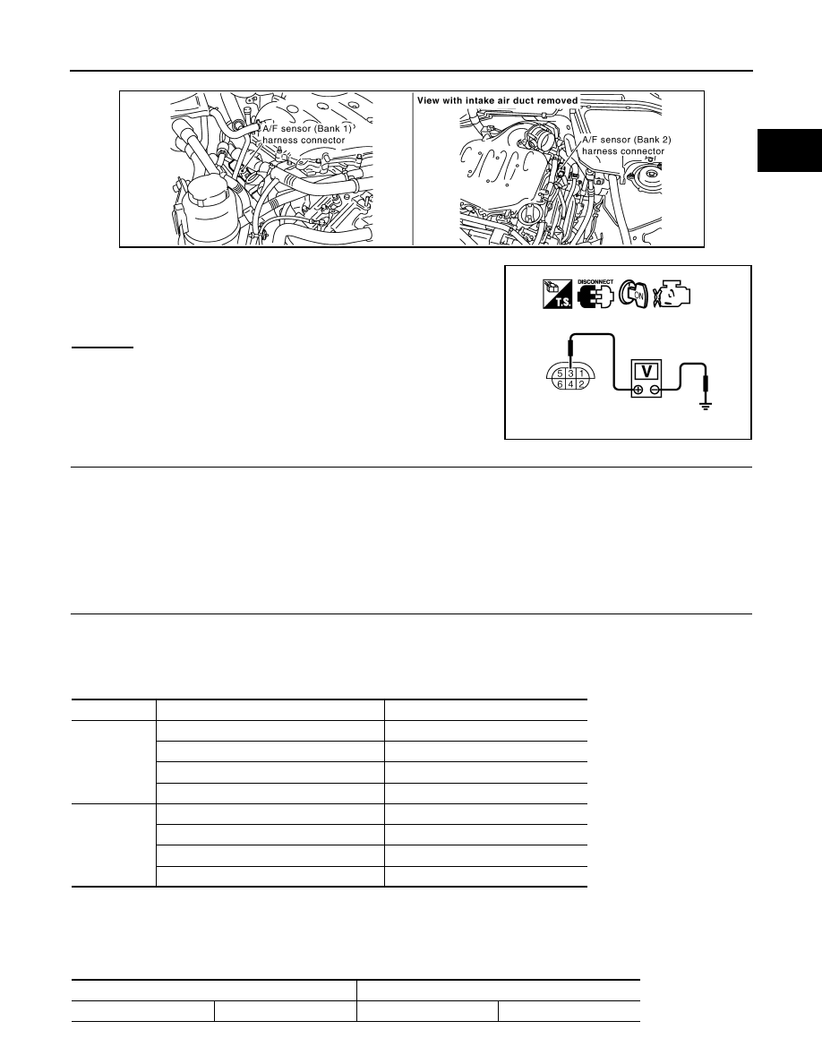
1.
Disconnect air fuel ratio (A/F) sensor 1 harness connector.
2.
Turn ignition switch ON.
3.
Check voltage between air fuel ratio (A/F) sensor 1 terminal 3
and ground with CONSULT-III or tester.
OK or NG
OK
>> GO TO 8.
NG
>> GO TO 7.
7.
DETECT MALFUNCTIONING PART
Check the following.
• Harness connectors E64, F65
• IPDM E/R harness connector E7
• 10A fuse
• Harness for open or short between air fuel ratio (A/F) sensor 1 and fuse
>> Repair or replace harness or connectors.
8.
CHECK AIR FUEL RATIO (A/F) SENSOR 1 INPUT SIGNAL CIRCUIT
1.
Turn ignition switch OFF.
2.
Disconnect ECM harness connector.
3.
Check harness continuity between the following terminals.
Refer to Wiring Diagram.
4.
Check harness continuity between the following terminals and ground.
Refer to Wiring Diagram.
Voltage: Battery voltage
PBIB2190E
PBIB1683E
A/F sensor 1 terminal
ECM terminal
Bank1
1
16
2
75
5
35
6
56
Bank 2
1
76
2
77
5
57
6
58
Continuity should exist.
Bank 1
Bank 2
A/F sensor 1 terminal
ECM terminal
A/F sensor 1 terminal
ECM terminal

EC-540
< SERVICE INFORMATION >
[VQ35DE]
DTC P2A00, P2A03 A/F SENSOR 1
5.
Also check harness for short to ground and short to power.
OK or NG
OK
>> GO TO 9.
NG
>> Repair open circuit or short to ground or short to power in harness or connectors.
9.
CHECK AIR FUEL RATIO (A/F) SENSOR 1 HEATER
EC-158, "Component Inspection"
OK or NG
OK
>> GO TO 10.
NG
>> GO TO 11.
10.
CHECK INTERMITTENT INCIDENT
Perform
OK or NG
OK
>> GO TO 11.
NG
>> Repair or replace.
11.
REPLACE AIR FUEL RATIO (A/F) SENSOR 1
Replace malfunctioning air fuel ratio (A/F) sensor 1.
CAUTION:
• Discard any air fuel ratio (A/F) sensor which has been dropped from a height of more than 0.5 m
(19.7 in) onto a hard surface such as a concrete floor; use a new one.
• Before installing new air fuel ratio (A/F) sensor, clean exhaust system threads using Heated Oxygen
Sensor Thread Cleaner tool J-43897-18 or J-43897-12 and approved anti-seize lubricant.
>> GO TO 12.
12.
CONFIRM A/F ADJUSTMENT DATA
1.
Turn ignition switch ON.
2.
Select “A/F ADJ-B1” and “A/F ADJ-B2” in “DATA MONITOR” mode with CONSULT-III.
3.
Make sure that “0.000” is displayed on CONSULT-III screen.
OK or NG
OK
>> INSPECTION END
NG
>> GO TO 13.
13.
CLEAR THE SELF-LEARNING DATA.
With CONSULT-III
1.
Start engine and warm it up to normal operating temperature.
2.
Select “SELF-LEARNING CONT” in “WORK SUPPORT” mode with CONSULT-III.
3.
Clear the self-learning control coefficient by touching “CLEAR”.
Without CONSULT-III
1.
Start engine and warm it up to normal operating temperature.
2.
Turn ignition switch OFF.
1
16
1
76
2
75
2
77
5
35
5
57
6
56
6
58
Continuity should not exist.
Нет комментариевНе стесняйтесь поделиться с нами вашим ценным мнением.
Текст