Infiniti FX35 / FX45. Manual — part 181
BCM (BODY CONTROL MODULE)
BCS-5
< SERVICE INFORMATION >
C
D
E
F
G
H
I
J
L
M
A
B
BCS
N
O
P
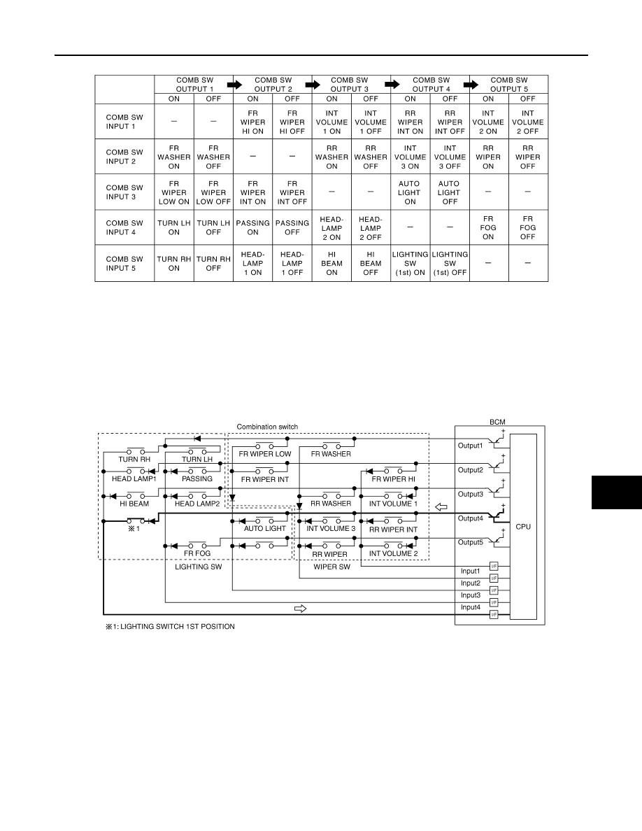
BCM reads operation status of combination switch using combinations shown in table below.
NOTE:
Headlamp system has a dual switch.
Sample Operation: (When Lighting Switch 1ST Position Turned ON)
• When lighting switch 1ST position is turned ON, contact in combination switch turns ON. At this time if OUT-
PUT 4 transistor is activated, BCM detects that voltage changes in INPUT 5.
• When OUTPUT 4 transistor is ON, BCM detects that voltage changes in INPUT 5, and judges that lighting
switch 1ST position is ON. Then BCM sends tail lamp and clearance lamp request signal to IPDM E/R using
CAN communication.
• When OUTPUT 4 transistor is activated again, BCM detects that voltage changes in INPUT 5, and recog-
nizes that lighting switch 1ST position is continuously ON.
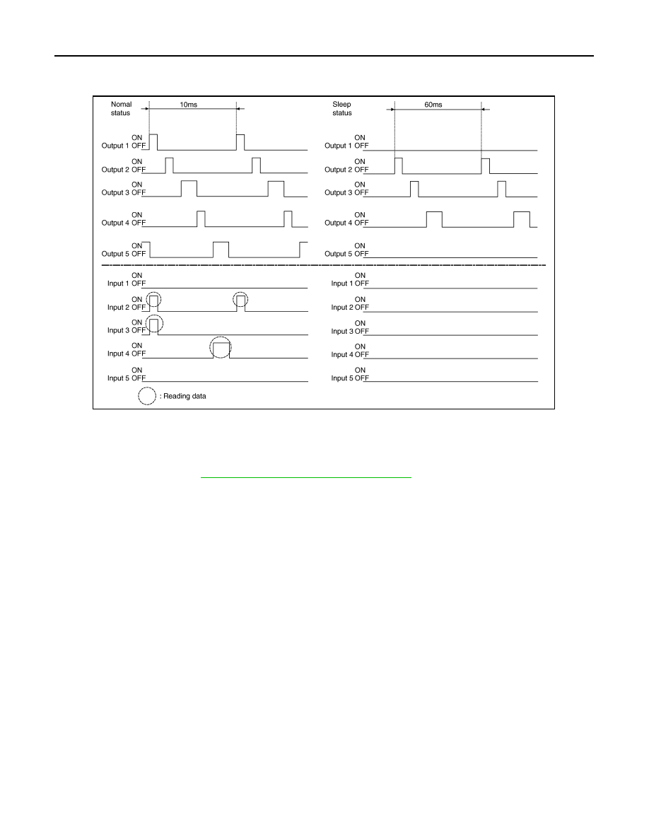
NOTE:
Each OUTPUT terminal transistor is activated at 10 ms intervals. Therefore after switch is turned ON, electri-
cal loads are activated with time delay. But this time delay is so short that it cannot be detected by human
senses.
Operation Mode
Combination switch reading function has operation modes shown below.
1.
Normal status
When BCM is not in sleep status, OUTPUT terminals (1-5) send out ON signal every 10 ms.
2.
Sleep status
SKIA4959E
PKID0854E
BCS-6
< SERVICE INFORMATION >
BCM (BODY CONTROL MODULE)
When BCM is in sleep status, transistors of OUTPUT 1 and 5 stop the output, and BCM enters low power
mode. Mean while OUTPUT 2, 3, and 4 send out ON signal every 60 ms, and accept input from lighting
switch system.
CAN COMMUNICATION CONTROL
CAN communication allows a high rate of information transmission through the two communication lines (CAN
L line, CAN H line) connecting the various control units in the system. Each control unit transmits/receives
data but selectively reads required data only. For details of signals that are transmitted/received by BCM via
CAN communication, refer to
LAN-43, "CAN System Specification Chart"
.
BCM STATUS CONTROL
BCM changes its status depending on the operation status in order to save power consumption.
1.
CAN communication status
• With ignition switch ON, CAN communicates with other control units normally.
• Control by BCM is being operated properly.
• When ignition switch is OFF, switching to sleep mode is possible.
• Even when ignition switch is OFF, if CAN communication with IPDM E/R and combination meter is
active, CAN communication status is active.
2.
Sleep transient status
• This status shuts down CAN communication when ignition switch is turned OFF.
• It transmits sleep request signal to IPDM E/R and combination meter.
• 2 seconds after CAN communication of all control units stops, sleep transient status is switched to CAN
communication inactive status.
3.
CAN communication inactive status
• With ignition switch OFF, CAN communication is not active.
• With ignition switch OFF, control performed only by BCM is active.
• 3 seconds after CAN communication of all control units stops, CAN communication inactive status is
switched to sleep status.
4.
Sleep status
• BCM is activated with low power mode.
• CAN communication is not active.
• When CAN communication operation is detected, it switches to CAN communication status.
• When a state of the following switches changes, it switches to CAN communication state.
- Key switch
- Hazard switch
PKIC4919E

BCM (BODY CONTROL MODULE)
BCS-7
< SERVICE INFORMATION >
C
D
E
F
G
H
I
J
L
M
A
B
BCS
N
O
P
- Door lock/unlock switch
- Front door switch (driver side, passenger side)
- Rear door switch (LH, RH)
- Back door opener switch
- Combination switch (passing, lighting switch 1ST position, front fog lamp)
- Key fob (lock/unlock signal)
- Key cylinder switch
• When control performed only by BCM is required by switch, it shifts to CAN communication inactive
mode.
• Operation mode of combination switch reading function is changed.
SYSTEMS CONTROLLED BY BCM DIRECTLY
NOTE:
Power supply only. No system control.
SYSTEMS CONTROLLED BY BCM AND IPDM E/R
SYSTEMS CONTROLLED BY BCM AND COMBINATION METER
SYSTEMS CONTROLLED BY BCM AND INTELLIGENT KEY UNIT
SYSTEMS CONTROLLED BY BCM, COMBINATION METER AND IPDM E/R
System
Reference
Power door lock system
Remote keyless entry system
Power window system
NOTE
Sunroof
NOTE
Room lamp timer
Rear wiper and washer system
System
Reference
Panic alarm
•
•
Theft warning system
IVIS (NATS)
Headlamp
Daytime light system
Auto light system
Front fog lamp
• Parking, license plate, side marker and tail lamps
• Exterior lamp battery saver control
Front wiper and washer system
Rear window defogger
System
Reference
Warning chime
Turn signal and hazard warning lamps
Tire pressure monitoring system
System
Reference
Intelligent Key system

BCS-8
< SERVICE INFORMATION >
BCM (BODY CONTROL MODULE)
MAJOR COMPONENTS AND CONTROL SYSTEM
System
Reference
Oil pressure warning lamp
System
Input
Output
Remote control entry system
Key fob
• All-door locking actuator
• Fuel lid Lock actuator
• Turn signal lamp (LH, RH)
• Combination meter
Intelligent Key system
Intelligent Key unit
• All-door locking actuator
• Fuel lid Lock actuator
• Turn signal lamp (LH, RH)
• Combination meter
Power door lock system
• Power window main switch
(door lock and unlock switch)
• Power window sub switch (passenger side)
(door lock and unlock switch)
All-door locking actuator
Power supply (IGN) to power window, sunroof
Ignition power supply
Power window and sunroof system
Power supply (BAT) to power window, sunroof
and power seat
Battery power supply
Power window, sunroof system and
power seat
Panic alarm
• Key switch
• Key fob
IPDM E/R
Theft warning system
• All-door switch
• Hood switch
• Key fob
• Power window main switch (door lock and
unlock switch)
• Power window sub switch (passenger side)
(door lock and unlock switch)
• IPDM E/R
• Security indicator lamp
Auto light system
• Optical sensor
• Combination switch
• Ignition switch
IPDM E/R
Exterior lamp battery saver control
• Ignition switch
• Combination switch
IPDM E/R
Headlamp
Combination switch
IPDM E/R
Daytime light system
• Combination meter
• ECM
• Combination switch
• Ignition switch
IPDM E/R
Parking, license plate, side marker and tail
lamps
Combination switch
IPDM E/R
Front fog lamp
Combination switch
IPDM E/R
Turn signal lamp
• Combination switch
• Ignition switch
• Turn signal lamp
• Combination meter
Hazard lamp
Hazard switch
• Turn signal lamp
• Combination meter
Room lamp timer
• Key switch
• Key fob
• Power window main switch (door lock and
unlock switch)
• Front door switch driver side
• All-door switch
Interior room lamp
Key warning chime
• Key switch
• Front door switch driver side
Combination meter
(warning buzzer)
Нет комментариевНе стесняйтесь поделиться с нами вашим ценным мнением.
Текст