Infiniti FX35 / FX45. Manual — part 893
REAR FINAL DRIVE ASSEMBLY
RFD-27
< SERVICE INFORMATION >
C
E
F
G
H
I
J
K
L
M
A
B
RFD
N
O
P
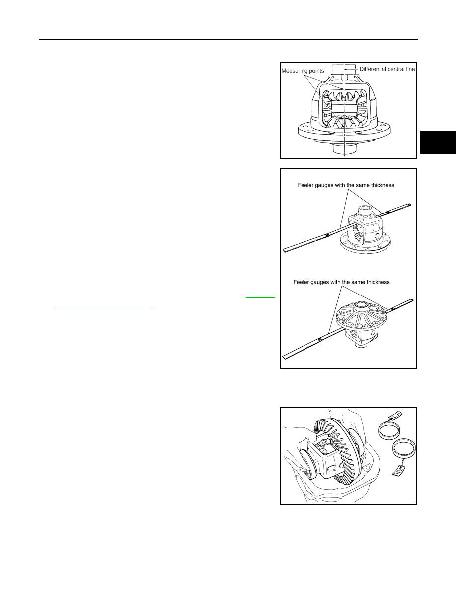
Differential Side Gear Clearance
• Assemble the differential parts if they are disassembled. Refer to "Differential Assembly".
1.
Place differential case straight up so that side gear to be mea-
sured comes upward.
2.
Using feeler gauge, measure the clearance between side gear
back and differential case at 3 different points, while rotating
side gear. Average the 3 readings, and then measure the clear-
ance of the other side as well.
CAUTION:
To prevent side gear from tilting, insert feeler gauges with
the same thickness from both sides.
3.
If the back clearance is outside the specification, use a thicker/
thinner side gear thrust washer to adjust. Refer to
.
CAUTION:
Select a side gear thrust washer for right and left individually.
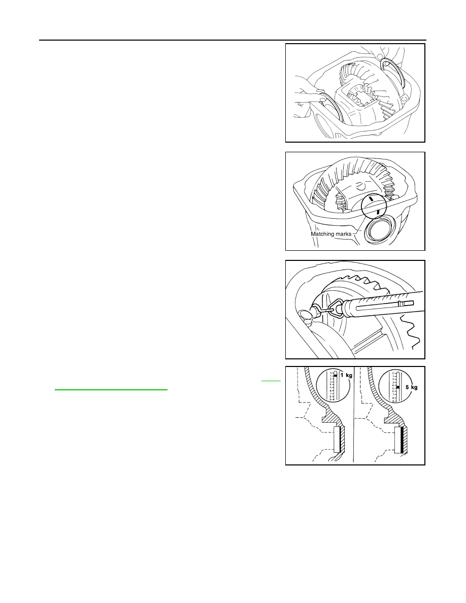
Side Bearing Preload
• Selecting carrier side bearing adjusting washers is required for successful completion of this procedure.
1.
Make sure all parts are clean. Also, make sure the bearings are
well lubricated with gear oil.
2.
Place the differential case, with side bearings and bearing races
installed, into gear carrier.
PDIA0460E
Side gear back clearance specification:
0.2 mm (0.008 in) or less.
(Each gear should rotate smoothly without excessive
resistance during differential motion.)
When the back clearance is large:
Use a thicker thrust washer.
When the back clearance is small:
Use a thinner thrust washer.
PDIA0576E
SPD527
RFD-28
< SERVICE INFORMATION >
REAR FINAL DRIVE ASSEMBLY
3.
Insert left and right original side bearing adjusting washers in
place between side bearings and gear carrier.
4.
Install bearing caps in their correct locations and tighten bearing
cap mounting bolts to the specified torque. Refer to "COMPO-
NENTS".
5.
Turn the carrier several times to seat the bearings.
6.
Measure the turning torque of the carrier at the drive gear
mounting bolts with a spring gauge.
7.
If the turning torque is outside the specification, use a thicker/
thinner side bearing adjusting washer to adjust. Refer to
38, "Inspection and Adjustment"
.
CAUTION:
Select a side bearing adjusting washer for right and left
individually.
8.
Record the total amount of washer thickness required for the correct carrier side bearing preload.
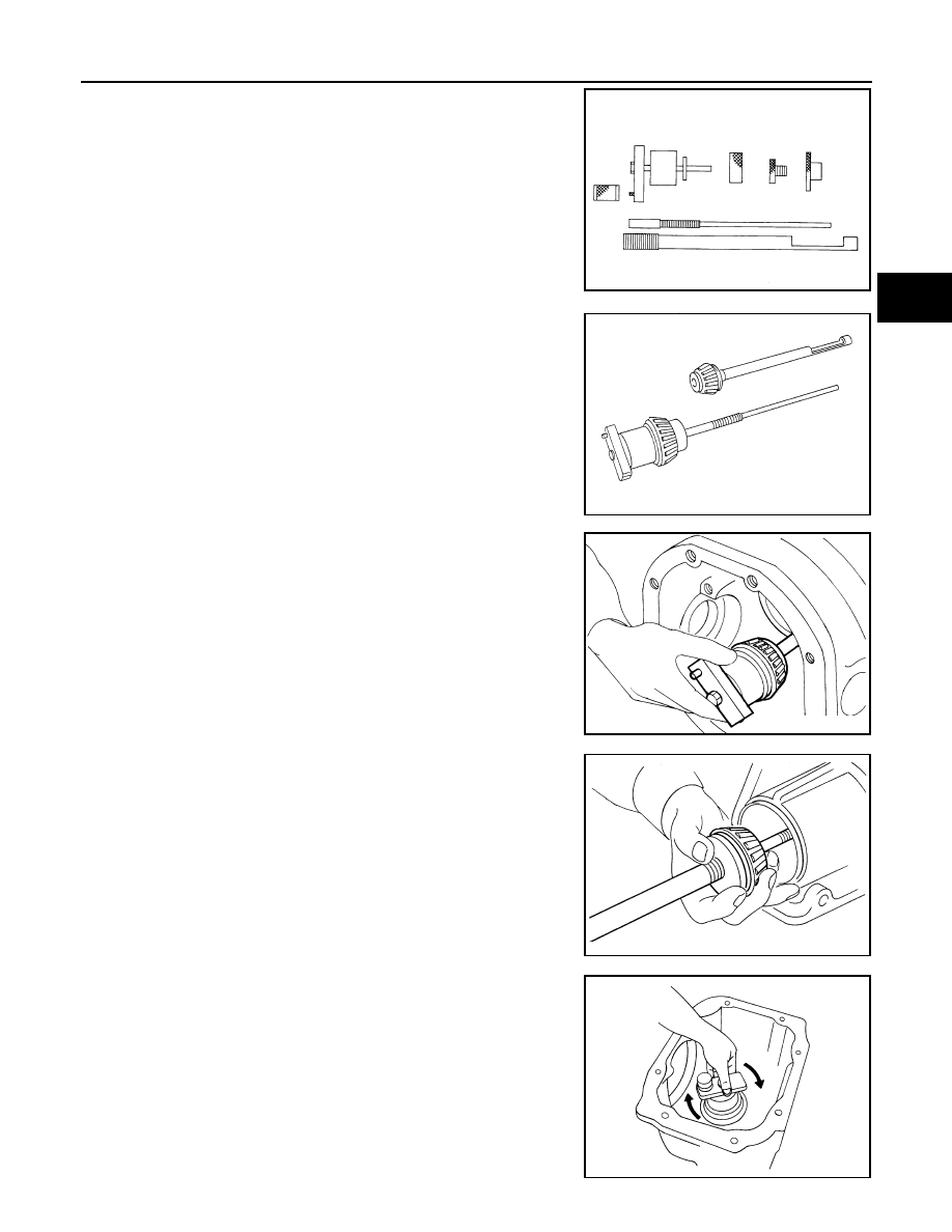
Pinion Gear Height
SPD558
SDIA1795E
Tool number
:
—
(J-8129)
Specification:
34.2 - 39.2 N (3.5 - 4.0 kg, 7.7 - 8.8 lb) of pulling force at
the drive gear bolt
SPD194A
If the turning torque is less than the specified range:
Use a thicker thrust washer.
If the turning torque is greater than the specification:
Use a thinner thrust washer.
SPD772
REAR FINAL DRIVE ASSEMBLY
RFD-29
< SERVICE INFORMATION >
C
E
F
G
H
I
J
K
L
M
A
B
RFD
N
O
P
1.
Make sure all parts are clean and that the bearings are well
lubricated.
2.
Assemble the pinion gear bearings into the differential shim
selector tool.
• Pinion front bearing; make sure the J-34309-3 pinion front
bearing seat is secured tightly against the J-34309-2 gauge
anvil. Then turn the pinion front bearing pilot, J-34309-5, to
secure the bearing in its proper position.
• Pinion rear bearing; the pinion rear bearing pilot, J-34309-8,
is used to center the pinion rear bearing only. The pinion rear
bearing locking seat, J-34309-4, is used to lock the bearing to
the assembly.
• Installation of J-34309-9 and J-34309-16; place a suitable
2.5 mm (0.098 in) thick plain washer between J-34309-9 and
J-34309-16. Both surfaces of J-34309-9 and J-34309-16 must
be parallel with a clearance of 2.5 mm (0.098 in).
3.
Install the pinion rear bearing inner race into gear carrier. Then
place the pinion preload shim selector tool, J-34309-1, gauge
screw assembly.
4.
Assemble the pinion front bearing inner race and the J-34309-2
gauge anvil. Assemble them together with the J-34309-1 gauge
screw in gear carrier. Make sure that the pinion height gauge
plate, J-34309-16, will turn a full 360 degrees. Tighten the two
sections together by hand.
5.
Turn the assembly several times to seat the bearings.
Tool number
:
—
(J-34309)
SPD769
SPD197A
SPD893
SPD199A
SPD770

RFD-30
< SERVICE INFORMATION >
REAR FINAL DRIVE ASSEMBLY
6.
Measure the turning torque at the end of the J-34309-2 gauge
anvil using preload gauge.
7.
Place the J-34309-11 “R200A” pinion height adapter onto the
gauge plate and tighten it by hand.
CAUTION:
Make sure all machined surfaces are clean.
8.
Position the side bearing discs, J-25269-4, and arbor firmly into
the side bearing bores. Install the bearing caps and tighten bear-
ing cap mounting bolts to the specified torque. Refer to "COM-
PONENTS".
9.
Select the correct standard pinion height adjusting washer thick-
ness. Select by using a standard gauge of 3 mm (0.12 in) and
your J-34309-101 feeler gauge. Measure the distance between
the J-34309-11 pinion height adapter including the standard
gauge and the arbor.
10. Write down exact measurement (the value of feeler gauge).
Tool number
: ST3127S000 (J-25765- A)
Turning torque specification:
1.0 - 1.3 N·m (0.11 - 0.13 kg-m, 9 - 11 in-lb)
PDIA0566E
SPD208A
SPD211A
SPD204A
SPD775
Нет комментариевНе стесняйтесь поделиться с нами вашим ценным мнением.
Текст