Infiniti FX35 / FX45. Manual — part 894
REAR FINAL DRIVE ASSEMBLY
RFD-31
< SERVICE INFORMATION >
C
E
F
G
H
I
J
K
L
M
A
B
RFD
N
O
P
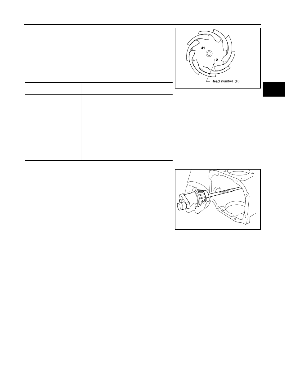
11. Correct the pinion height washer size by referring to the “pinion
head number”.
There are two numbers painted on the drive pinion. The first
one refers to the drive pinion and drive gear as a matched
set. This number should be the same as the number on the
drive gear. The second number is the “pinion head height
number”. It refers to the ideal pinion height from standard
for quietest operation. Use the following chart to determine
the correct pinion height washer.
12. Select the correct pinion height adjusting washer. Refer to
RFD-38, "Inspection and Adjustment"
13. Remove the J-34309 differential shim selector tool from the final
drive housing. Then disassemble to retrieve the pinion bearings.
ASSEMBLY
Drive Pinion Assembly
Pinion head height number
Add or remove from the standard pinion height ad-
justing washer thickness measurement
- 6
- 5
- 4
- 3
- 2
- 1
0
+1
+2
+3
+4
+5
+6
Add 0.06 mm (0.0024 in)
Add 0.05 mm (0.0020 in)
Add 0.04 mm (0.0016 in)
Add 0.03 mm (0.0012 in)
Add 0.02 mm (0.0008 in)
Add 0.01 mm (0.0004 in)
Use the selected washer thickness
Subtract 0.01 mm (0.0004 in)
Subtract 0.02 mm (0.0008 in)
Subtract 0.03 mm (0.0012 in)
Subtract 0.04 mm (0.0016 in)
Subtract 0.05 mm (0.0020 in)
Subtract 0.06 mm (0.0024 in)
SPD542
SPD205A
RFD-32
< SERVICE INFORMATION >
REAR FINAL DRIVE ASSEMBLY
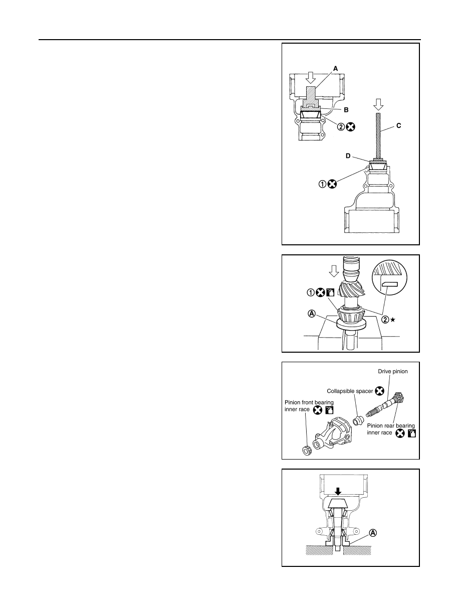
1.
Install front bearing outer race (1) and rear bearing outer race
(2) using drifts.
CAUTION:
• At first, using a hammer, tap bearing outer race until it
becomes flat to gear carrier.
• Never reuse pinion front and rear bearing outer race.
2.
Select drive pinion height adjusting washer. Refer to "Pinion
Gear Height".
3.
Install selected drive pinion height adjusting washer (2) to drive
pinion. Press pinion rear bearing inner race (1) to it, using drift.
CAUTION:
• Pay attention to the direction of pinion height adjusting
washer. (Assemble as shown in the figure.)
• Never reuse pinion rear bearing inner race.
4.
Assemble collapsible spacer to drive pinion.
CAUTION:
Never reuse collapsible spacer.
5.
Apply gear oil to pinion rear bearing, and assemble drive pinion
into gear carrier.
6.
Apply gear oil to pinion front bearing, and assemble pinion front
bearing inner race to drive pinion assembly.
CAUTION:
Never reuse pinion front bearing inner race.
7.
Using suitable spacer (A), press the pinion front bearing inner
race to drive pinion as far as drive pinion nut can be tightened.
Tool number
A: ST30720000 (J-25405)
B: KV40105230 (
—
)
C: ST30611000 (J-25742-1)
D: ST30613000 (J-25742-3)
PDIA0761J
Tool number
A: ST30901000 (J-26010-01)
PDIA0805J
PDIA0492E
PDIA0762J

REAR FINAL DRIVE ASSEMBLY
RFD-33
< SERVICE INFORMATION >
C
E
F
G
H
I
J
K
L
M
A
B
RFD
N
O
P
8.
Using the drift, install front oil seal as shown in figure.
CAUTION:
• Never reuse oil seal.
• When installing, never incline oil seal.
• Apply multi-purpose grease onto oil seal lips, and gear oil
onto the circumference of oil seal.
9.
Install companion flange (1).
NOTE:
When reusing drive pinion, align the matching mark (B) of drive
pinion with the matching mark (A) of companion flange, and then
install companion flange (1).
10. Apply anti-corrosion oil to the thread and seat of drive pinion lock nut, and temporarily tighten drive pinion
lock nut to drive pinion.
CAUTION:
Never reuse drive pinion lock nut.
11. Adjust to the drive pinion lock nut tightening torque and pinion
bearing preload torque.
CAUTION:
• Adjust to the lower limit of the drive pinion lock nut tight-
ening torque first.
• If the preload torque exceeds the specified value, replace
collapsible spacer and tighten it again to adjust. Never
loosen drive pinion lock nut to adjust the preload torque.
• After adjustment, rotate drive pinion back and forth 2 to 3
times to check for unusual noise, rotation malfunction,
and other malfunctions.
12. Install differential case assembly. Refer to "Differential Assem-
bly".
CAUTION:
Never install rear cover yet.
13. Check and adjust drive gear runout, tooth contact, drive gear to drive pinion backlash, and companion
flange runout. Refer to "Drive Gear Runout", "Tooth Contact", "Backlash", "Companion Flange Runout".
Recheck above items. Readjust the above description, if necessary.
14. Check total preload torque. Refer to "Total Preload Torque".
15. Install rear cover. Refer to "Differential Assembly".
Tool number
A: ST30720000 (J-25405)
PDIA0764J
PDIA0750J
Tool number
A: ST3127S000 (J-25765-A)
Drive pinion lock nut tightening torque:
147 - 323 N·m (15 - 32 kg-m, 109 - 238 ft-lb)
Drive pinion bearing preload:
2.65 - 3.23 N·m (0.27 - 0.32 kg-m, 24 - 28 in-lb)
PDIA0765J
RFD-34
< SERVICE INFORMATION >
REAR FINAL DRIVE ASSEMBLY
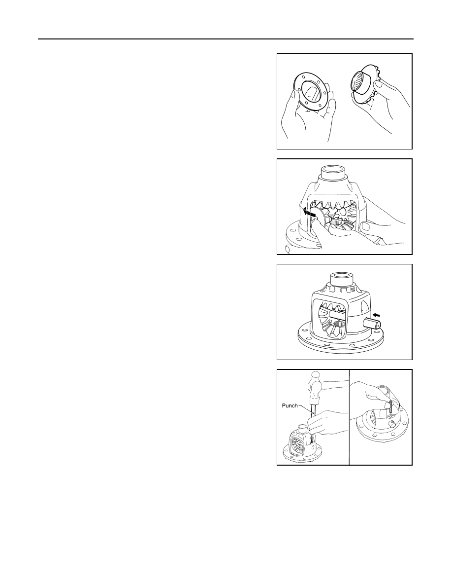
Differential Assembly
1.
Install side gear thrust washers with the same thickness as the
ones installed prior to disassembly or reinstall the old ones on
the side gears.
2.
Install side gears and thrust washers into differential case.
CAUTION:
Make sure that the circular clip is installed to side gears.
3.
Align 2 pinion mate gears in diagonally opposite positions, then
rotate and install them into differential case after installing thrust
washer to pinion mate gear.
4.
Align the lock pin holes on differential case with shaft, and install
pinion mate shaft.
5.
Measure side gear end play. If necessary, select the appropriate
side gear thrust washers. Refer to "Differential Side Gear Clear-
ance".
6.
Drive a lock pin into pinion mate shaft, using a punch.
Make sure lock pin is flush with differential case.
CAUTION:
Never reuse lock pin.
SDIA0193J
SDIA2025E
SDIA0195J
SPD030
Нет комментариевНе стесняйтесь поделиться с нами вашим ценным мнением.
Текст