Infiniti FX35 / FX45. Manual — part 970
WW-2
Inspection of Front Wiper and Washer Switch Cir-
cuit . . . . . . . . . . . . . . . . . . ..
Removal and Installation of Rear Wiper and
Washer Switch . . . . . . . . . . . . . ....
Removal and Installation of Washer Tank . . . ..
Removal and Installation of Front and Rear Wash-
er pump . . . . . . . . . . . . . . . . ..
POWER SOCKET . . . . . . . . . . . ..
Wiring Diagram - P/SCKT - . . . . . . . . ....
Removal and Installation of Front Power Socket -
1 . . . . . . . . . . . . . . . . . . . ..
Removal and Installation of Front Power Socket -
2 . . . . . . . . . . . . . . . . . . . ..
Removal and Installation of Rear Power Socket . .
Removal and Installation of Luggage Room Power
Socket . . . . . . . . . . . . . . . . . .
HORN . . . . . . . . . . . . . . . . .
Wiring Diagram - HORN - . . . . . . . . . ...
PRECAUTION
WW-3
< SERVICE INFORMATION >
C
D
E
F
G
H
I
J
L
M
A
B
WW
N
O
P
SERVICE INFORMATION
PRECAUTION
Precaution for Supplemental Restraint System (SRS) "AIR BAG" and "SEAT BELT
PRE-TENSIONER"
INFOID:0000000001612916
The Supplemental Restraint System such as “AIR BAG” and “SEAT BELT PRE-TENSIONER”, used along
with a front seat belt, helps to reduce the risk or severity of injury to the driver and front passenger for certain
types of collision. This system includes seat belt switch inputs and dual stage front air bag modules. The SRS
system uses the seat belt switches to determine the front air bag deployment, and may only deploy one front
air bag, depending on the severity of a collision and whether the front occupants are belted or unbelted.
Information necessary to service the system safely is included in the “SUPPLEMENTAL RESTRAINT SYS-
TEM” and “SEAT BELTS” of this Service Manual.
WARNING:
• To avoid rendering the SRS inoperative, which could increase the risk of personal injury or death in
the event of a collision which would result in air bag inflation, all maintenance must be performed by
an authorized NISSAN/INFINITI dealer.
• Improper maintenance, including incorrect removal and installation of the SRS, can lead to personal
injury caused by unintentional activation of the system. For removal of Spiral Cable and Air Bag
Module, see the “SUPPLEMENTAL RESTRAINT SYSTEM”.
• Do not use electrical test equipment on any circuit related to the SRS unless instructed to in this
Service Manual. SRS wiring harnesses can be identified by yellow and/or orange harnesses or har-
ness connectors.
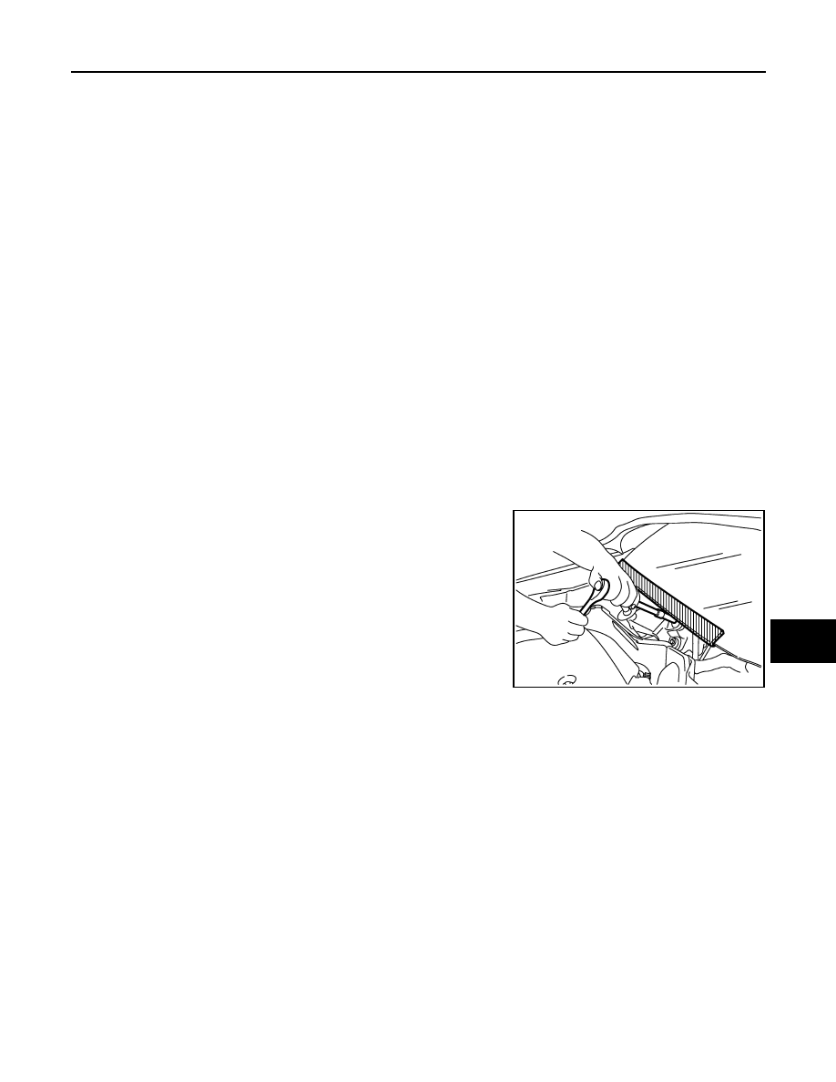
Precaution for Procedure without Cowl Top Cover
INFOID:0000000001612917
When performing the procedure after removing cowl top cover, cover
the lower end of windshield with urethane, etc.
PIIB3706J
WW-4
< SERVICE INFORMATION >
FRONT WIPER AND WASHER SYSTEM
FRONT WIPER AND WASHER SYSTEM
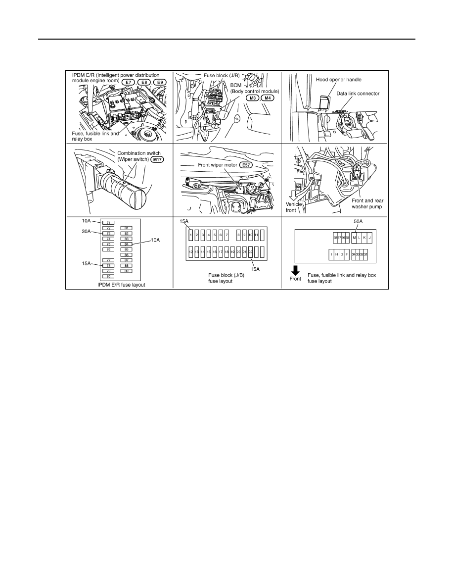
Component Parts and Harness Connector Location
INFOID:0000000001328542
System Description
INFOID:0000000001328543
• All front wiper relays (HI, LO) are included in IPDM E/R (intelligent power distribution module engine room).
• Wiper switch (combination switch) is composed of a combination of 5 output terminals and 5 input terminals.
Terminal combination status is read by BCM (body control module) when switch is turned ON.
• BCM controls front wiper LO, HI, and INT (intermittent) operation.
• IPDM E/R operates wiper motor according to CAN communication signals from BCM.
OUT LINE
Power is supplied at all times
• through 50 A fusible link (letter M, located in fuse, fusible link and relay box.)
• to BCM terminal 55,
• through 15 A fuse [No. 22, located in fuse block (J/B)]
• to BCM terminal 42,
• through 30 A fuse (No. 73, located in IPDM E/R)
• to front wiper relay, located in IPDM E/R,
• through 15 A fuse (No. 78, located in IPDM E/R) and
• through 10 A fuse (No. 71, located in IPDM E/R)
• to CPU located in IPDM E/R.
When the ignition switch is ON or START position, power is supplied
• to ignition relay located in IPDM E/R, from battery direct,
• through 15 A fuse [No. 1, located in fuse block (J/B)]
• to BCM terminal 38,
• through ignition relay, located in IPDM E/R
• to front wiper relay, located in IPDM E/R
• to front wiper high relay, located in IPDM E/R and
• to CPU located in IPDM E/R,
• through 10 A fuse (No. 84, located in IPDM E/R)
• through IPDM E/R terminal 44
• to combination switch terminal 14.
Ground is supplied
PKIC9701E

FRONT WIPER AND WASHER SYSTEM
WW-5
< SERVICE INFORMATION >
C
D
E
F
G
H
I
J
L
M
A
B
WW
N
O
P
• to BCM terminals 49 and 52
• through grounds M35, M45 and M85,
• to IPDM E/R terminals 38 and 60
• through grounds E21, E50 and E51,
• to combination switch terminal 12
• through grounds M35, M45 and M85.
LOW SPEED WIPER OPERATION
When wiper switch is in LOW position, BCM detects low speed wiper ON signal by BCM wiper switch reading
function.
BCM sends front wiper request signal (LO) through CAN communication
• from BCM terminals 39 and 40
• to IPDM E/R terminals 48 and 49.
When IPDM E/R receives front wiper request signal (LO), it turns ON front wiper relay located in IPDM E/R,
power is supplied
• through front wiper relay
• through front wiper high relay
• through IPDM E/R terminal 21
• to front wiper motor terminal 1.
Ground is supplied
• to front wiper motor terminal 2
• through grounds E21, E50 and E51.
With power and ground supplied, the front wiper motor operates at low speed.
HIGH SPEED WIPER OPERATION
When wiper switch is in HI position, BCM detects high speed wiper ON signal by BCM wiper switch reading
function.
BCM sends front wiper request signal (HI) through CAN communication
• from BCM terminals 39 and 40
• to IPDM E/R terminals 48 and 49.
When IPDM E/R receives front wiper request signal (HI), it turns ON front wiper relay (located in IPDM E/R),
power is supplied
• through front wiper relay
• through front wiper high relay
• through IPDM E/R terminal 31
• to front wiper motor terminal 4.
Ground is supplied
• to front wiper motor terminal 2
• through grounds E21, E50 and E51.
With power and ground supplied, the front wiper motor operates at high speed.
INTERMITTENT OPERATION
Front wiper intermittent operation delay interval is determined from a combination of 3 switches (intermittent
operation dial position 1, 2, and 3) and vehicle speed signal.
Speed dependent wiper controlled mode can be changed by the function setting of CONSULT-III or display.
During each intermittent operation delay interval, BCM sends front wiper request signal to IPDM E/R.
Wiper Dial Position Setting
Example: For wiper intermittent dial position 1
Wiper intermittent dial position
Intermittent operation
interval
Combination switch
INT VOLUME 1
INT VOLUME 2
INT VOLUME 3
1
Short
↑
↓
Long
ON
ON
ON
2
ON
ON
OFF
3
ON
OFF
OFF
4
OFF
OFF
OFF
5
OFF
OFF
ON
6
OFF
ON
ON
7
OFF
ON
OFF
Нет комментариевНе стесняйтесь поделиться с нами вашим ценным мнением.
Текст