Infiniti FX35 / FX45. Manual — part 633
FUEL INJECTOR AND FUEL TUBE
EM-49
< SERVICE INFORMATION >
[VQ35DE]
C
D
E
F
G
H
I
J
K
L
M
A
EM
N
P
O
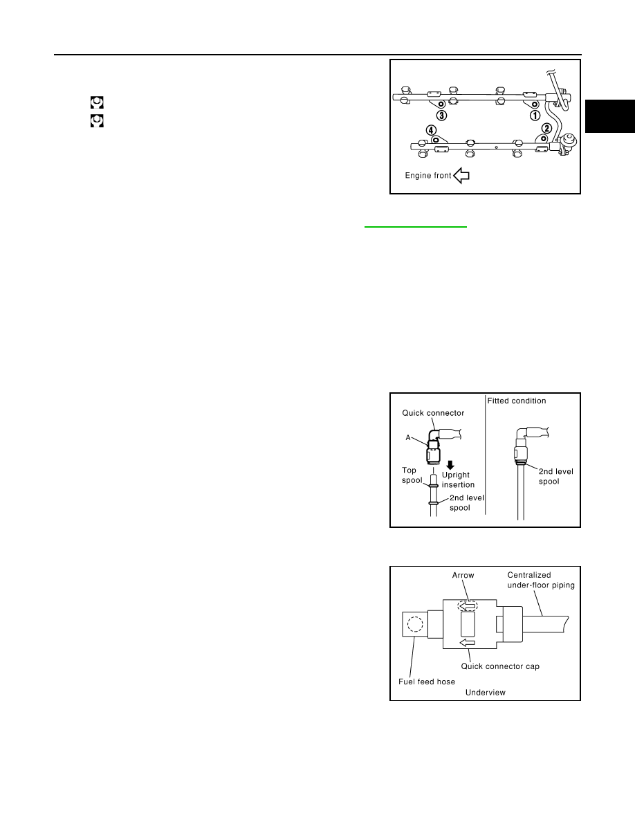
• Tighten mounting bolts in two steps in numerical order as
shown in the figure.
6.
Connect injector sub-harness.
7.
Install intake manifold collectors (upper and lower). Refer to
8.
Install fuel sub-tube on rear end of intake manifold collector (lower).
9.
Connect fuel feed hose (with damper).
• Handling procedure of O-ring is the same as that of fuel damper and fuel sub-tube.
• Insert fuel damper straight into fuel sub-tube.
• Tighten mounting bolts evenly in turn.
• After tightening mounting bolts, make sure that there is no gap between flange and fuel sub-tube.
10. Connect quick connector between fuel feed hose (with damper) and centralized under-floor piping con-
nection as follows:
a.
Make sure no foreign substances are deposited in and around centralized under-floor piping and quick
connector, and no damage on them.
b.
Thinly apply new engine oil around centralized under-floor piping from tip end to spool end.
c.
Align center to insert quick connector straightly into centralized under-floor piping.
• Insert quick connector to centralized under-floor piping until
top spool is completely inside quick connector, and 2nd level
spool exposes right below quick connector.
CAUTION:
• Hold “A” position as shown in the figure when inserting
centralized under-floor piping into quick connector.
• Carefully align center to avoid inclined insertion to pre-
vent damage to O-ring inside quick connector.
• Insert until you hear a “click” sound and actually feel the
engagement.
• To avoid misidentification of engagement with a similar
sound, be sure to perform the next step.
d.
Pull quick connector by hand holding “A” position. Make sure it is completely engaged (connected) so that
it does not come out from centralized under-floor piping.
e.
Install quick connector cap to quick connector connection.
• Install quick connector cap with arrow on surface facing in
direction of quick connector (fuel feed hose side).
CAUTION:
If quick connector cap cannot be installed smoothly, quick
connector may have not been installed correctly. Check the
connection again.
11. Install in the reverse order of removal after this step.
INSPECTION AFTER INSTALLATION
Check on Fuel Leakage
1.
Turn ignition switch “ON” (with the engine stopped). With fuel pressure applied to fuel piping, make sure
there are no fuel leaks at connection points.
1st step
: 10.1 N·m (1.0 kg-m, 7 ft-lb)
2nd step
: 23.6 N·m (2.4 kg-m, 17 ft-lb)
KBIA1296E
PBIC2471E
KBIA1298E
EM-50
< SERVICE INFORMATION >
[VQ35DE]
FUEL INJECTOR AND FUEL TUBE
NOTE:
Use mirrors for checking at points out of clear sight.
2.
Start the engine. With engine speed increased, make sure again that there are no fuel leaks at connection
points.
CAUTION:
Do not touch the engine immediately after stopped, as the engine becomes extremely hot.
ROCKER COVER
EM-51
< SERVICE INFORMATION >
[VQ35DE]
C
D
E
F
G
H
I
J
K
L
M
A
EM
N
P
O
ROCKER COVER
Component
INFOID:0000000001325726
Removal and Installation
INFOID:0000000001325727
REMOVAL
1.
Remove engine cover with power tool. Refer to
2.
Release the fuel pressure. Refer to
3.
Drain engine coolant, or when water hoses are disconnected, attach plug to prevent engine coolant leak-
age. Refer to
CO-10, "Changing Engine Coolant"
and
.
CAUTION:
Perform this step when the engine is cold.
4.
Remove intake manifold collectors (upper and lower). Refer to
.
5.
Separate engine harness removing their brackets from rocker covers.
6.
Remove ignition coil. Refer to
7.
Remove PCV hoses from rocker covers.
8.
Remove PCV valve and O-ring from rocker cover (right bank), if necessary.
9.
Remove oil filler cap and oil catcher from rocker cover (left bank), if necessary.
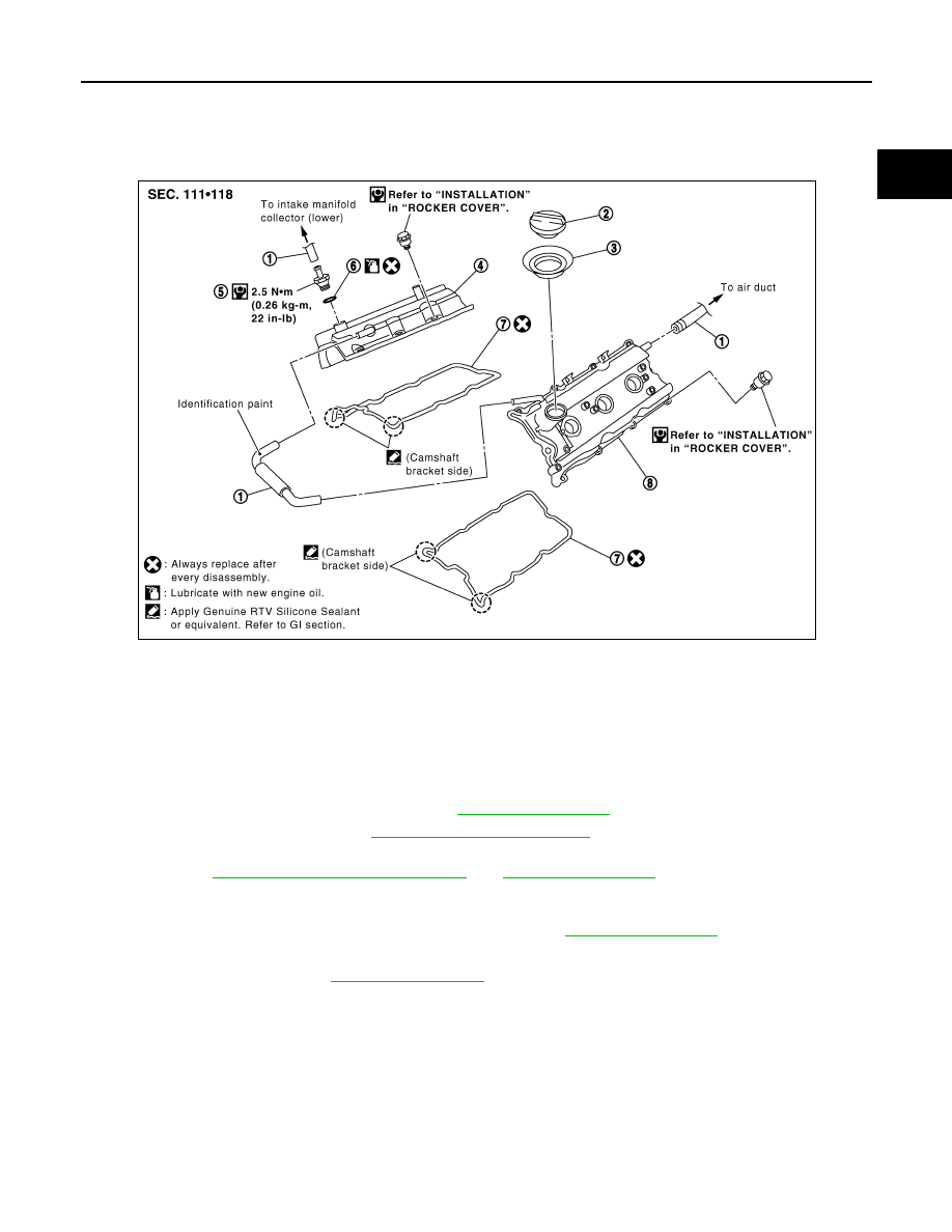
1.
PCV hose
2.
Oil filler cap
3.
Oil catcher
4.
Rocker cover (right bank)
5.
PCV control valve
6.
O-ring
7.
Rocker cover gasket
8.
Rocker cover (left bank)
PBIC2303E
EM-52
< SERVICE INFORMATION >
[VQ35DE]
ROCKER COVER
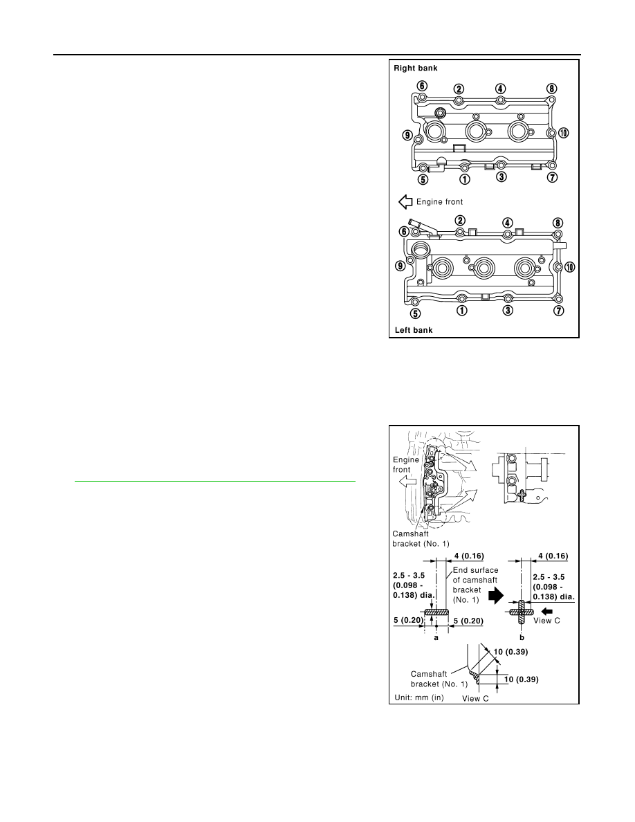
10. Loosen mounting bolts with power tool in reverse order as
shown in the figure.
11. Remove rocker cover gaskets from rocker covers.
12. Use a scraper to remove all trances of liquid gasket from cylinder head and camshaft bracket (No. 1).
CAUTION:
Do not scratch or damage the mating surface when cleaning off old liquid gasket.
INSTALLATION
1.
Apply liquid gasket with the tube presser (commercial service
tool) to joint part among rocker cover, cylinder head and cam-
shaft bracket (No. 1) as follows:
Use Genuine RTV Silicone Sealant or equivalent. Refer to
GI-44, "Recommended Chemical Product and Sealant"
NOTE:
The figure shows an example of left bank side [zoomed in shows
camshaft bracket (No. 1)].
a.
Refer to the figure “a” to apply liquid gasket to joint part of cam-
shaft bracket (No. 1) and cylinder head.
b.
Refer to the figure “b” to apply liquid gasket to the figure “a”
squarely.
2.
Install new rocker cover gasket to rocker cover.
3.
Install rocker cover.
• Check if rocker cover gasket is not dropped from installation groove of rocker cover.
KBIA0985E
PBIC2474E
Нет комментариевНе стесняйтесь поделиться с нами вашим ценным мнением.
Текст