Infiniti FX35 / FX45. Manual — part 265

BRC-46
< SERVICE INFORMATION >
[VDC/TCS/ABS]
TROUBLE DIAGNOSIS FOR SYSTEM
Does anything besides “ST ANG SEN SIGNAL” appear on self-diagnostic results display?
YES
>> Inspect and repair the indicated items. Then perform self-diagnosis again.
NO
>> Perform adjustment of steering angle sensor neutral position. Then GO TO 2.
2.
CHECK SELF DIAGNOSIS RESULTS (2)
Turn ignition switch OFF and ON to erase self-diagnostic results, and perform ABS actuator and electric unit
(control unit) self-diagnosis again.
Does anything appear on self-diagnostic results display?
YES
>> Replace steering angle sensor. Then perform adjustment of neutral position and perform self-
diagnosis again.
NO
>> INSPECTION END
DTC C1145 YAW RATE SENSOR
INFOID:0000000001569717
DTC C1146 SIDE G-SEN CIRCUIT
INFOID:0000000001569718
DTC C1155 BR FLUID LEVEL LOW
INFOID:0000000001327687
INSPECTION PROCEDURE
1.
CHECK SELF-DIAGNOSTIC RESULTS
1.
Check fluid level in brake fluid reservoir tank. If the level is low, add brake fluid.
2.
Clear the stored self-diagnostic results and check self-diagnostic results.
Is the above displayed in the self-diagnosis display item?
YES
>> GO TO 2.
NO
>> INSPECTION END
2.
CHECK CONNECTOR
1.
Disconnect brake fluid level switch connector and ABS actuator and electric unit (control unit) connector
and check terminal for deformation, disconnection, looseness, and so on. If any malfunction is found,
repair or replace terminal.
2.
Securely reconnect connectors and perform self-diagnosis again.
OK or NG
OK
>> Connector terminal contact is loose, damaged, open or shorted.
NG
>> GO TO 3.
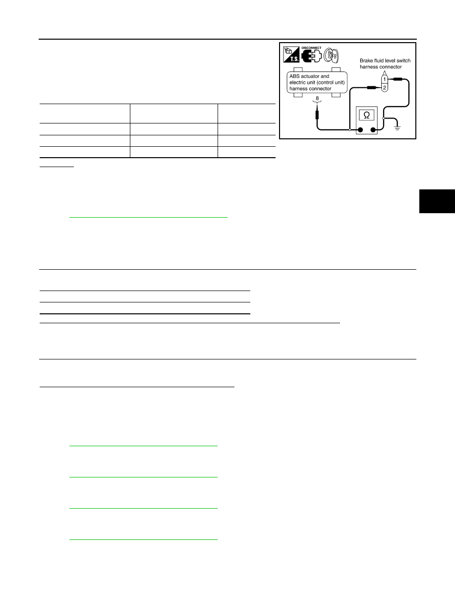
3.
CHECK HARNESS BETWEEN BRAKE FLUID LEVEL SWITCH AND ABS ACTUATOR AND ELECTRIC
UNIT (CONTROL UNIT)
Self-diagnostic results
ST ANG SEN SIGNAL
Self-diagnostic results
BR FLUID LEVEL LOW
TROUBLE DIAGNOSIS FOR SYSTEM
BRC-47
< SERVICE INFORMATION >
[VDC/TCS/ABS]
C
D
E
G
H
I
J
K
L
M
A
B
BRC
N
O
P
1.
Turn ignition switch OFF and disconnect brake fluid level switch
connector E52 and ABS actuator and electric unit (control unit)
connector E56.
2.
Check continuity between brake fluid level switch harness con-
nector and ABS actuator and electric unit (control unit) harness
connector.
OK or NG
OK
>> Connect connectors and perform an ABS actuator and electric unit (control unit) self-diagnosis.
NG
>> If open or short in harness, repair or replace applied harness.
DTC C1156 ST ANG SEN COM CIR
INFOID:0000000001569719
BRC-48, "DTC U1000 CAN COMM CIRCUIT"
DTC C1160 DECEL G SEN SET
INFOID:0000000001327689
INSPECTION PROCEDURE
1.
CHECK SELF- DIAGNOSTIC RESULTS (1)
Check self-diagnostic results.
Does anything besides “DECEL G SEN SET” appear on self-diagnostic results display?
YES
>> Inspect and repair the indicated items. Then perform self-diagnosis again.
NO
>> Perform calibration of decel G sensor. Then GO TO 2.
2.
CHECK SELF-DIAGNOSIS RESULTS (2)
Turn ignition switch OFF and ON to erase self-diagnostic results, and perform ABS actuator and electric unit
(control unit) self-diagnosis again.
Does anything appear on self-diagnostic results display?
YES
>> Replace yaw rate/side/decel G sensor. Then perform calibration of decel G sensor and perform
self-diagnosis again.
NO
>> INSPECTION END
DTC C1164 CV 1
INFOID:0000000001569724
BRC-40, "DTC C1120 FR LH IN ABS SOL"
.
DTC C1165 CV 2
INFOID:0000000001569725
BRC-40, "DTC C1120 FR LH IN ABS SOL"
.
DTC C1166 SV 1
INFOID:0000000001569726
BRC-40, "DTC C1120 FR LH IN ABS SOL"
.
DTC C1167 SV 2
INFOID:0000000001569727
BRC-40, "DTC C1120 FR LH IN ABS SOL"
.
ABS actuator and electric unit
(control unit)
Brake fluid level switch
Continuity
8
1
Yes
8
Ground
No
Ground
2
Yes
SFIA1193E
Self-diagnostic results
DECEL G SEN SET
BRC-48
< SERVICE INFORMATION >
[VDC/TCS/ABS]
TROUBLE DIAGNOSIS FOR SYSTEM
DTC C1170 VARIANT CODING
INFOID:0000000001569755
BRC-37, "DTC C1110 CONTROLLER FAILURE"
.
DTC U1000 CAN COMM CIRCUIT
INFOID:0000000001327690
INSPECTION PROCEDURE
1.
CHECK CONNECTOR
1.
Turn ignition switch OFF, disconnect the ABS actuator and electric unit (control unit) connector, and check
the terminal for deformation, disconnection, looseness, and so on. If there is a malfunction, repair or
replace the terminal.
2.
Reconnect connector to perform self-diagnosis.
Is “CAN COMM CIRCUIT” or “ST ANG SEN COM CIR” displayed in the self-diagnosis display items?
YES
>> Print out the self-diagnostic results, and refer to
LAN-43, "CAN System Specification Chart"
NO
>> Connector terminal connection is loose, damaged, open, or shorted.
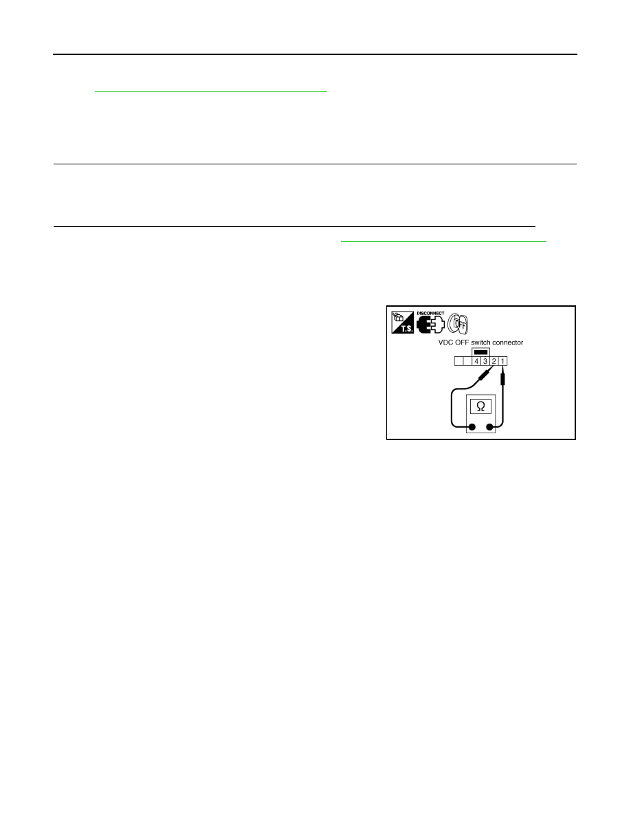
Component Inspection
INFOID:0000000001327691
VDC OFF SWITCH
• Turn ignition switch OFF and disconnect VDC OFF switch connec-
tor, and check continuity between VDC OFF switch connector M32
terminals 1 and 2.
1 -2
: Continuity should exist when pushing
switch.
Continuity should not exist when releasing
switch.
SFIA1203E

TROUBLE DIAGNOSIS FOR SYMPTOMS
BRC-49
< SERVICE INFORMATION >
[VDC/TCS/ABS]
C
D
E
G
H
I
J
K
L
M
A
B
BRC
N
O
P
TROUBLE DIAGNOSIS FOR SYMPTOMS
Excessive ABS Function Operation Frequency
INFOID:0000000001327692
1.
CHECK FRONT AND REAR AXLE
Make sure there is no excessive looseness in the front and rear axles.
OK or NG
OK
>> GO TO 2.
NG
>> Check front or rear axle system.
2.
CHECK WHEEL SENSOR
Perform following inspection for wheel sensor:
• Sensor mount and damage inspection
• Sensor rotor mount and damage inspection
• Sensor connector connection inspection
• Sensor harness inspection
OK or NG
OK
>> GO TO 3.
NG
>> Replace sensor or sensor rotor.
3.
CHECK ABS WARNING LAMP DISPLAY
Make sure warning lamp turns off approximately 2 seconds after the ignition switch is turned ON or when driv-
ing.
OK or NG
OK
>> Normal
NG
>> Perform self-diagnosis. Refer to
.
Unexpected Pedal Reaction
INFOID:0000000001327693
1.
CHECK BRAKE PEDAL STROKE
Check brake pedal stroke.
Is the stroke too long?
YES
>> • Bleed air from brake piping.
• Check brake pedal, brake booster, and master cylinder mount for play, looseness, and brake
system for fluid leaks, etc. If any malfunctions are found, make repair.
NO
>> GO TO 2.
2.
CHECK FUNCTION
Disconnect ABS actuator and electric unit (control unit) connector E56 and make sure that braking force is suf-
ficient when ABS in not operating. After the inspection, reconnect connector.
OK or NG
OK
>> CHECK WHEEL SENSOR. Refer to
BRC-49, "Excessive ABS Function Operation Frequency"
NG
>> Check brake system.
The Braking Distance Is Long
INFOID:0000000001327694
CAUTION:
On slippery road surfaces, the stopping distance might be longer with the ABS operating than when
the ABS is not operating.
1.
CHECK FUNCTION
Disconnect ABS actuator and electric unit (control unit) connector E56 to deactivate ABS. In this condition,
check stopping distance. After inspection, connect connector.
OK or NG
OK
>> • Bleed air from brake piping.
• Check brake system.
NG
>> CHECK WHEEL SENSOR. Refer to
Нет комментариевНе стесняйтесь поделиться с нами вашим ценным мнением.
Текст