Infiniti FX35 / FX45. Manual — part 263
BRC-38
< SERVICE INFORMATION >
[VDC/TCS/ABS]
TROUBLE DIAGNOSIS FOR SYSTEM
1.
Disconnect ABS actuator and electric unit (control unit) connector. Then reconnect it securely.
2.
Perform self-diagnosis again.
Do any self-diagnosis item appear?
YES
>> GO TO 3.
NO
>> Poor connection. Repair or replace the applicable connector.
3.
CHECK ABS MOTOR AND MOTOR RELAY POWER SUPPLY CIRCUIT
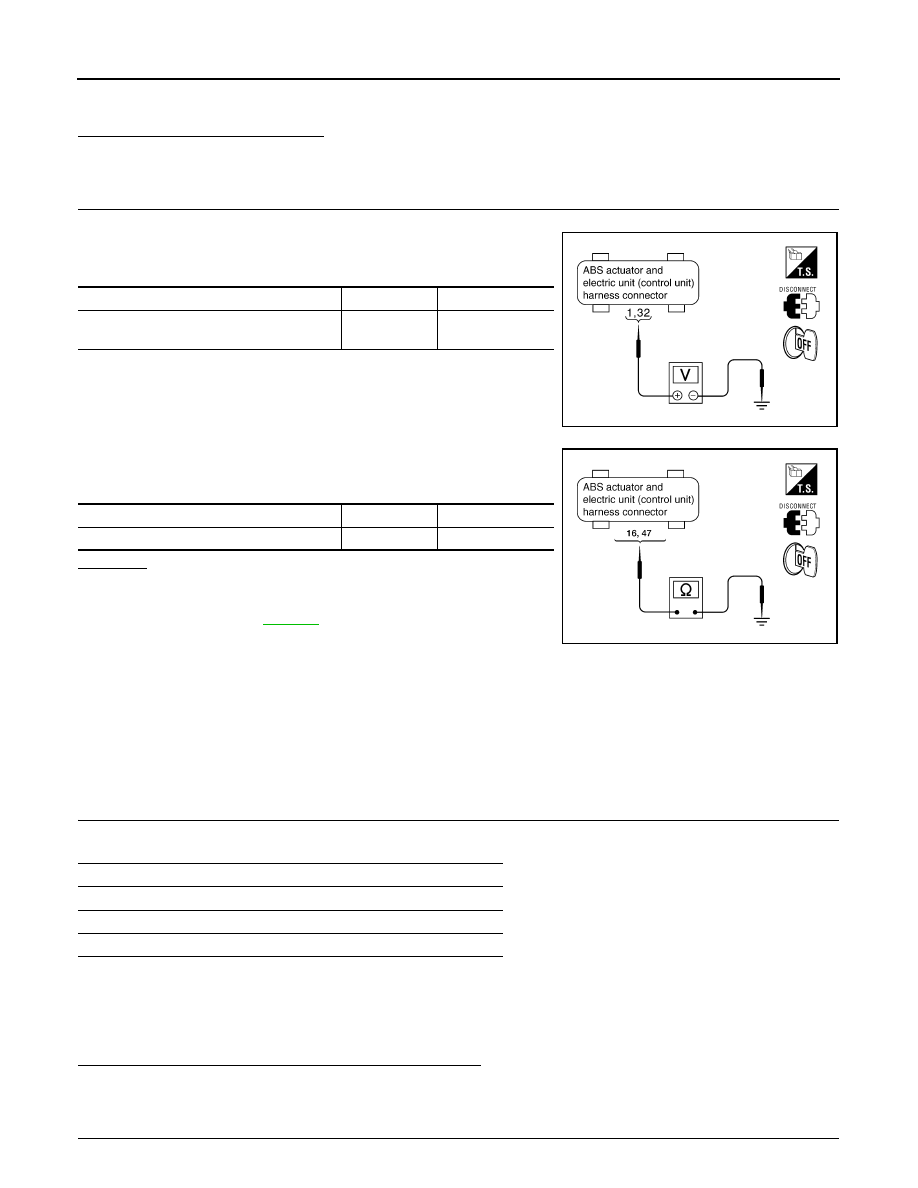
1.
Turn ignition switch OFF and disconnect ABS actuator and electric unit (control unit) connector E56.
2.
Check voltage between ABS actuator and electric unit (control
unit) harness connector and ground.
3.
Check continuity between ABS actuator and electric unit (control
unit) harness connector and ground.
OK or NG
OK
>> Perform self-diagnosis again. If the same result
appears, replace ABS actuator and electric unit (control
unit). Refer to
NG
>> Repair harness or connectors.
DTC C1113 G-SENSOR
INFOID:0000000001327682
CAUTION:
Sudden turns (such as spin turns, acceleration turns), drifting, etc. may cause the G sensor circuit
indicate a malfunction. However, this is not a malfunction, if normal operation can be resumed after
restarting engine.
INSPECTION PROCEDURE
1.
CHECK SELF-DIAGNOSTIC RESULTS
Check the self-diagnostic results.
CAUTION:
When on a turntable, such as at a parking structure entrance, or when on a moving object with engine
running, VDC OFF indicator lamp might turn on and self-diagnosis using CONSULT-III the yaw rate
sensor system might be displayed, but in this case there is no malfunction in yaw rate sensor circuit.
As soon as vehicle leaves turntable or moving object, restart engine to return the system to normal.
Is the above displayed in the self-diagnosis display items?
YES
>> GO TO 2.
NO
>> INSPECTION END
2.
CHECK CONNECTOR
ABS actuator and electric unit (control unit)
Ground
Voltage
1, 32
—
Battery voltage
(Approx. 12 V)
SFIA1198E
ABS actuator and electric unit (control unit)
Ground
Continuity
16, 47
—
Yes
SFIA1197E
Self-diagnostic results
YAW RATE SENSOR
SIDE G-SEN CIRCUIT
G-SENSOR (AWD models)
TROUBLE DIAGNOSIS FOR SYSTEM
BRC-39
< SERVICE INFORMATION >
[VDC/TCS/ABS]
C
D
E
G
H
I
J
K
L
M
A
B
BRC
N
O
P
1.
Disconnect G sensor connector and ABS actuator and electric unit (control unit) connector and check ter-
minals for deformation, disconnection, looseness, and so on. If any malfunction is found, repair or replace
terminal.
2.
Reconnect connectors and perform a ABS actuator and electric unit (control unit) self-diagnosis again.
OK or NG
OK
>> Connector terminal contact is loose, damaged, open or shorted.
NG
>> GO TO 3.
3.
CHECK G SENSOR HARNESS
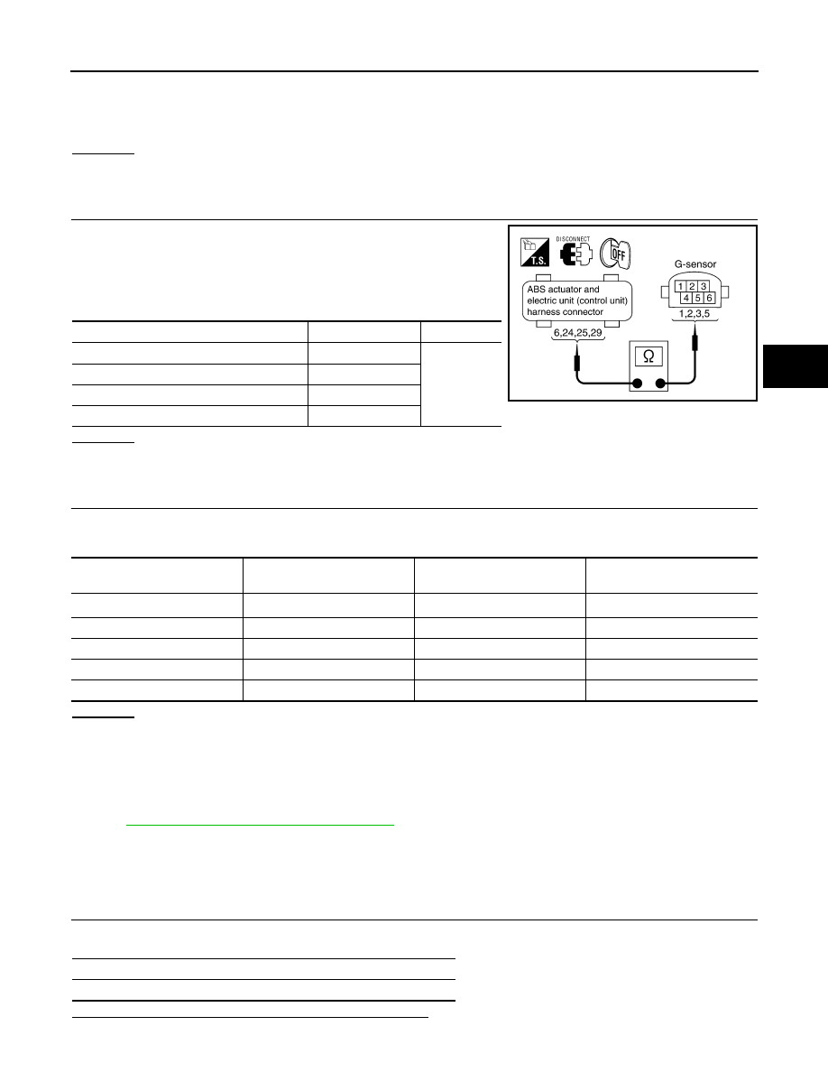
1.
Turn ignition switch OFF and disconnect G sensor connector
M79 (2WD models) or M71 (AWD models) and ABS actuator
and electric unit (control unit) connector E56.
2.
Check continuity between ABS actuator and electric unit (control
unit) harness connector and G sensor harness connector.
OK or NG
OK
>> GO TO 4.
NG
>> If the open or short in harness, repair or replace harness.
4.
CHECK G SENSOR
1.
Connect G sensor connector and ABS actuator and electric unit (control unit) connector.
2.
Use CONSULT-III “DATA MONITOR” to check if G sensor are normal.
OK or NG
OK
>> Perform ABS actuator and electric unit (control unit) self-diagnosis again.
NG
>> Replace malfunctioning G sensor, and then perform self-diagnosis for ABS actuator and electric
unit (control unit) again.
DTC C1115 ABS SENSOR [ABNORMAL SIGNAL]
INFOID:0000000001569698
BRC-34, "DTC C1101 RR RH SENSOR-1"
DTC C1116 STOP LAMP SW
INFOID:0000000001327686
INSPECTION PROCEDURE
1.
CHECK SELF-DIAGNOSTIC RESULTS
Check the self-diagnostic results.
Is the above displayed in the self-diagnosis display item?
ABS actuator and electric unit (control unit)
G sensor
Continuity
6
3
Yes
24
5
25
1
29
2
SFIA1192E
Vehicle status
Yaw rate sensor
(Data monitor standard)
Side G sensor
(Data monitor standard)
Decel G sensor (AWD models)
(Data monitor standard)
When stopped
−
4 to + 4 deg/s
−
1.1 to + 1.1 m/s
2
−
0.11 to + 0.11G
Right turn
Negative value
Negative value
—
Left turn
Positive value
Positive value
—
Speed up
—
—
Negative value
Speed down
—
—
Positive value
Self-diagnostic results
STOP LAMP SW
BRC-40
< SERVICE INFORMATION >
[VDC/TCS/ABS]
TROUBLE DIAGNOSIS FOR SYSTEM
YES
>> GO TO 2.
NO
>> INSPECTION END
2.
CHECK CONNECTOR
1.
Disconnect stop lamp switch connector and ABS actuator and electric unit (control unit) connector E56
and check terminals for deformation, disconnection, looseness, and so on. If any malfunction is found,
repair or replace terminal.
2.
Securely reconnect connectors.
3.
Perform self-diagnosis again.
OK or NG
OK
>> Connector terminal contact is loose, damaged, open or shorted.
NG
>> GO TO 3.
3.
CHECK STOP LAMP SWITCH
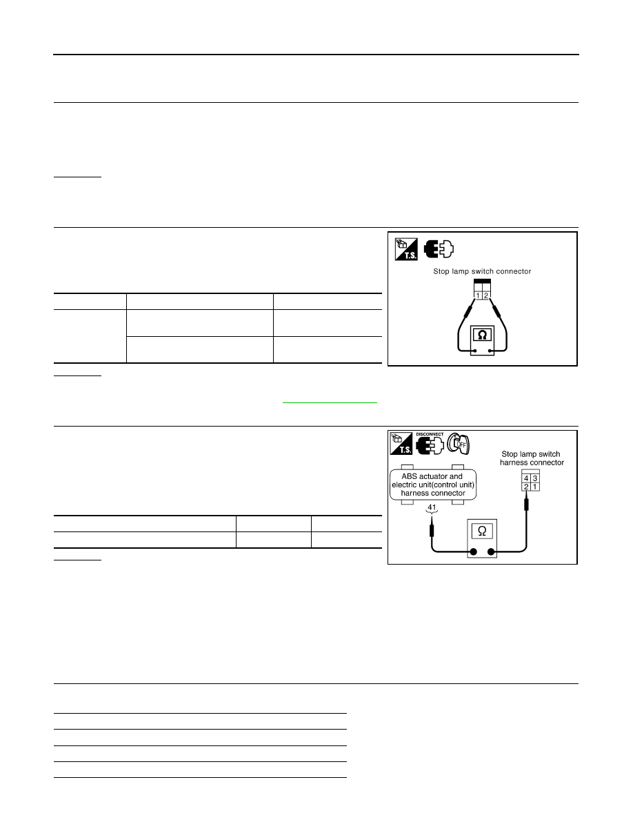
1.
Turn ignition switch OFF and disconnect stop lamp switch har-
ness connector.
2.
Operate stop lamp switch and check continuity between stop
lamp switch harness connector terminals.
OK or NG
OK
>> GO TO 4.
NG
>> Replace stop lamp switch. Refer to
.
4.
CHECK STOP LAMP SWITCH CIRCUIT
1.
Turn ignition switch OFF and disconnect stop lamp switch con-
nector E210 and ABS actuator and electric unit (control unit)
connector E56.
2.
Check continuity between stop lamp switch harness connector
and ABS actuator and electric unit (control unit) harness con-
nector.
OK or NG
OK
>> Connect connectors and perform an ABS actuator and
electric unit (control unit) self-diagnosis.
NG
>> Open or short in harness between stop lamp switch and ABS actuator and electric unit (control
unit). Repair or replace applied harness.
DTC C1120 FR LH IN ABS SOL
INFOID:0000000001327683
INSPECTION PROCEDURE
1.
CHECK SELF-DIAGNOSTIC RESULTS
Check the self-diagnostic results.
Terminal
Condition
Continuity
1
−
2
Release stop lamp switch
(When brake pedal is depressed.)
Yes
Push stop lamp switch
(When brake pedal is released.)
No
SFIA3392E
ABS actuator and electric unit (control unit)
Stop lamp switch
Continuity
41
2
Yes
SFIA1436E
Self-diagnostic results
FR LH IN ABS SOL
FR LH OUT ABS SOL
RR RH IN ABS SOL
TROUBLE DIAGNOSIS FOR SYSTEM
BRC-41
< SERVICE INFORMATION >
[VDC/TCS/ABS]
C
D
E
G
H
I
J
K
L
M
A
B
BRC
N
O
P
Is the above displayed in the self-diagnosis display items?
YES
>> GO TO 2.
NO
>> INSPECTION END
2.
CHECK CONNECTOR
1.
Disconnect ABS actuator and electric unit (control unit) connector check terminals for deformation, dis-
connection, looseness, and so on. If any malfunction is found, repair or replace terminal.
2.
Securely reconnect connector and perform self-diagnosis.
OK or NG
OK
>> Connector terminal contact is loose, damaged, open or shorted.
NG
>> GO TO 3.
3.
CHECK SOLENOID POWER AND GROUND CIRCUIT
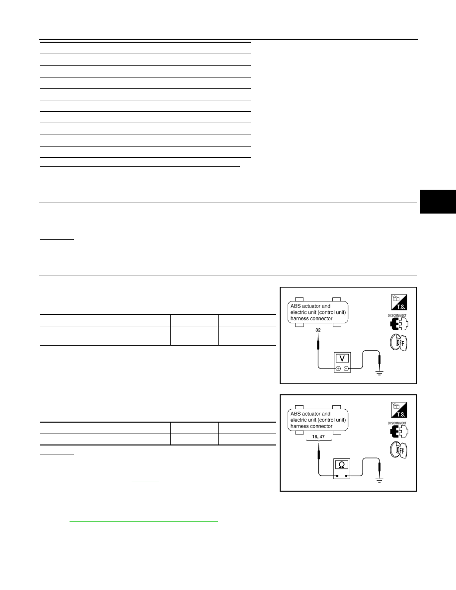
1.
Turn ignition switch OFF and disconnect ABS actuator and electric unit (control unit) connector E56.
2.
Check voltage between ABS actuator and electric unit (control
unit) harness connector and ground.
3.
Check continuity between ABS actuator and electric unit (control
unit) harness connector and ground.
OK or NG
OK
>> Perform self-diagnosis again. If the same results
appear, replace ABS actuator and electric unit (control
unit). Refer to
.
NG
>> Repair or replace harness or connectors.
DTC C1121 FR LH OUT ABS SOL
INFOID:0000000001569703
BRC-40, "DTC C1120 FR LH IN ABS SOL"
.
DTC C1122 FR RH IN ABS SOL
INFOID:0000000001569706
BRC-40, "DTC C1120 FR LH IN ABS SOL"
.
RR RH OUT ABS SOL
FR RH IN ABS SOL
FR RH OUT ABS SOL
RR LH IN ABS SOL
RR LH OUT ABS SOL
CV 1
CV 2
SV 1
SV 2
Self-diagnostic results
ABS actuator and electric unit (control unit)
Ground
Voltage
32
—
Battery voltage
(Approx. 12 V)
SFIA1196E
ABS actuator and electric unit (control unit)
Ground
Continuity
16, 47
—
Yes
SFIA1197E
Нет комментариевНе стесняйтесь поделиться с нами вашим ценным мнением.
Текст