Infiniti FX35 / FX45. Manual — part 264

BRC-42
< SERVICE INFORMATION >
[VDC/TCS/ABS]
TROUBLE DIAGNOSIS FOR SYSTEM
DTC C1123 FR RH OUT ABS SOL
INFOID:0000000001569707
BRC-40, "DTC C1120 FR LH IN ABS SOL"
.
DTC C1124 RR LH IN ABS SOL
INFOID:0000000001569708
BRC-40, "DTC C1120 FR LH IN ABS SOL"
.
DTC C1125 RR LH OUT ABS SOL
INFOID:0000000001569709
BRC-40, "DTC C1120 FR LH IN ABS SOL"
.
DTC C1126 RR RH IN ABS SOL
INFOID:0000000001569710
BRC-40, "DTC C1120 FR LH IN ABS SOL"
.
DTC C1127 RR RH OUT ABS SOL
INFOID:0000000001569711
BRC-40, "DTC C1120 FR LH IN ABS SOL"
.
DTC C1130 ENGINE SIGNAL 1
INFOID:0000000001327678
INSPECTION PROCEDURE
1.
CHECK SELF-DIAGNOSTIC RESULTS
Check the self-diagnostic results.
Is the above displayed in the self-diagnosis display items?
YES
>> GO TO 2.
NO
>> INSPECTION END
2.
CHECK ENGINE SYSTEM
1.
Perform an ECM self-diagnosis and repair or replace malfunctioning items. Perform ECM self-diagnosis
again.
2.
Perform ABS actuator and electric unit (control unit) self-diagnosis again.
OK or NG
OK
>> INSPECTION END
NG
>> Repair or replace malfunctioning items. Perform the self-diagnosis again.
DTC C1131 ENGINE SIGNAL 2
INFOID:0000000001569712
BRC-42, "DTC C1130 ENGINE SIGNAL 1"
DTC C1132 ENGINE SIGNAL 3
INFOID:0000000001569713
BRC-42, "DTC C1130 ENGINE SIGNAL 1"
DTC C1133 ENGINE SIGNAL 4
INFOID:0000000001569714
BRC-42, "DTC C1130 ENGINE SIGNAL 1"
DTC C1136 ENGINE SIGNAL 6
INFOID:0000000001569715
BRC-42, "DTC C1130 ENGINE SIGNAL 1"
Self-diagnostic results
ENGINE SIGNAL 1
ENGINE SIGNAL 2
ENGINE SIGNAL 3
ENGINE SIGNAL 4
ENGINE SIGNAL 6
TROUBLE DIAGNOSIS FOR SYSTEM
BRC-43
< SERVICE INFORMATION >
[VDC/TCS/ABS]
C
D
E
G
H
I
J
K
L
M
A
B
BRC
N
O
P
DTC C1140 ACTUATOR RLY
INFOID:0000000001569716
BRC-37, "DTC C1111 PUMP MOTOR"
DTC C1142 PRESS SEN CIRCUIT
INFOID:0000000001327680
INSPECTION PROCEDURE
1.
CHECK SELF-DIAGNOSTIC RESULTS
Check the self-diagnostic results.
Is the above displayed in the self-diagnosis display items?
YES
>> GO TO 2.
NO
>> INSPECTION END
2.
CHECK STOP LAMP SWITCH CONNECTOR
1.
Disconnect stop lamp switch connector and ABS actuator and electric unit (control unit) connector, check
terminals for deformation, disconnection, looseness, and so on. If any malfunction is found, repair or
replace terminal.
2.
Reconnect connectors and perform ABS actuator and electric unit (control unit) self-diagnosis again.
OK or NG
OK
>> Connector terminal contact is loose, damaged, open or shorted.
NG
>> GO TO 3.
3.
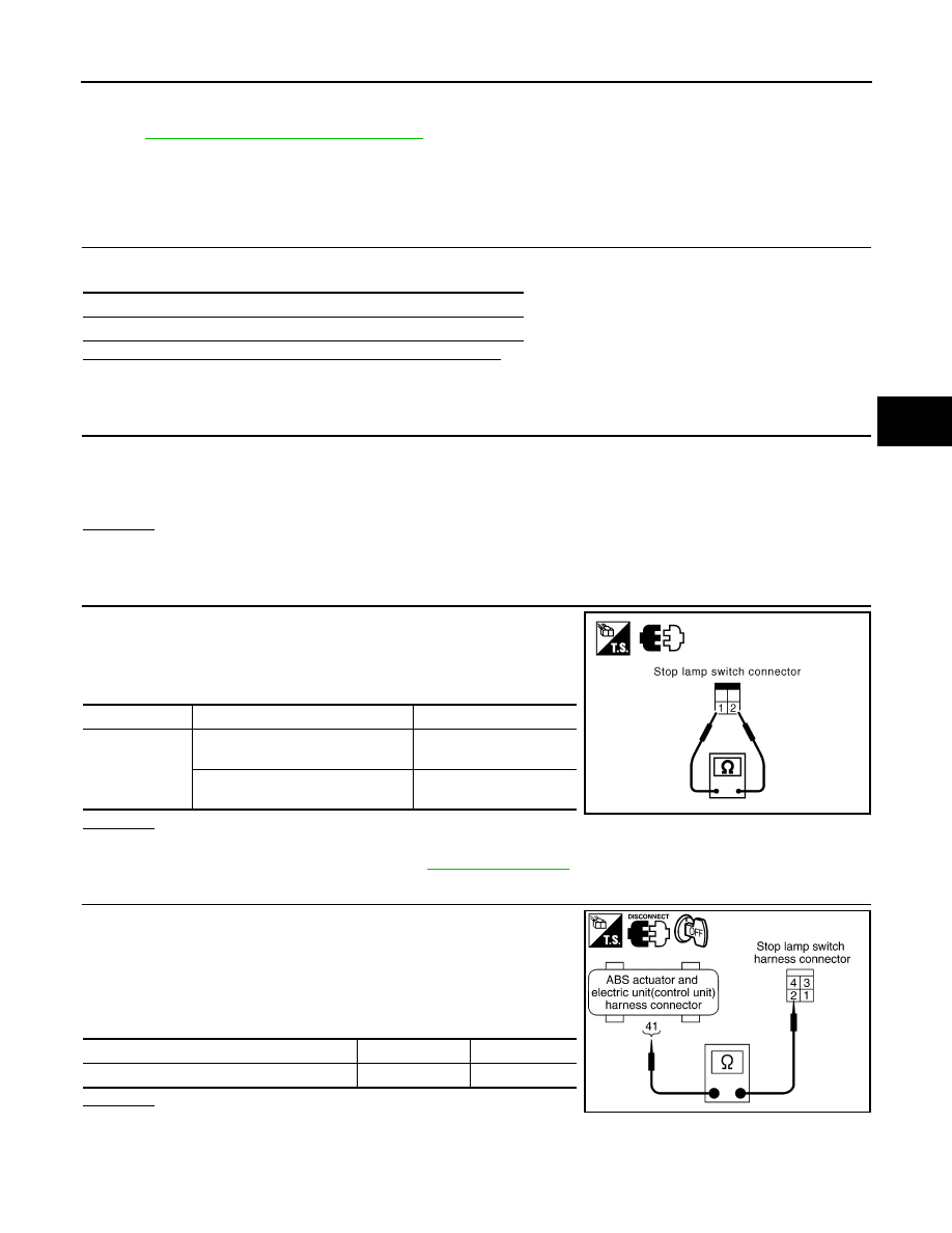
CHECK STOP LAMP SWITCH
1.
Turn ignition switch OFF and disconnect stop lamp switch har-
ness connector.
2.
Operate stop lamp switch and check continuity between stop
lamp switch harness connector terminals.
OK or NG
OK
>> GO TO 4.
NG
>> Replace stop lamp switch. Refer to
.
4.
CHECK STOP LAMP SWITCH CIRCUIT
1.
Turn ignition switch OFF and disconnect stop lamp switch con-
nector E210 and ABS actuator and electric unit (control unit)
connector E56.
2.
Check continuity between stop lamp switch harness connector
and ABS actuator and electric unit (control unit) harness con-
nector.
OK or NG
OK
>> GO TO 5.
NG
>> Open or short in harness between stop lamp switch and ABS actuator and electric unit (control
unit). Repair or replace applied harness.
Self-diagnostic results
PRESS SEN CIRCUIT
Terminal
Condition
Continuity
1
−
2
Release stop lamp switch
(When brake pedal is depressed.)
Yes
Push stop lamp switch
(When brake pedal is released.)
No
SFIA3392E
ABS actuator and electric unit (control unit)
Stop lamp switch
Continuity
41
2
Yes
SFIA1436E
BRC-44
< SERVICE INFORMATION >
[VDC/TCS/ABS]
TROUBLE DIAGNOSIS FOR SYSTEM
5.
CHECK PRESSURE SENSOR CONNECTOR
1.
Disconnect pressure sensor connector and ABS actuator and electric unit (control unit) connector, check
terminals for deformation, disconnection, looseness, and so on. If any malfunction is found, repair or
replace terminal.
2.
Reconnect connectors and perform ABS actuator and electric unit (control unit) self-diagnosis again.
OK or NG
OK
>> Connector terminal contact is loose, damaged, open or shorted.
NG
>> GO TO 6.
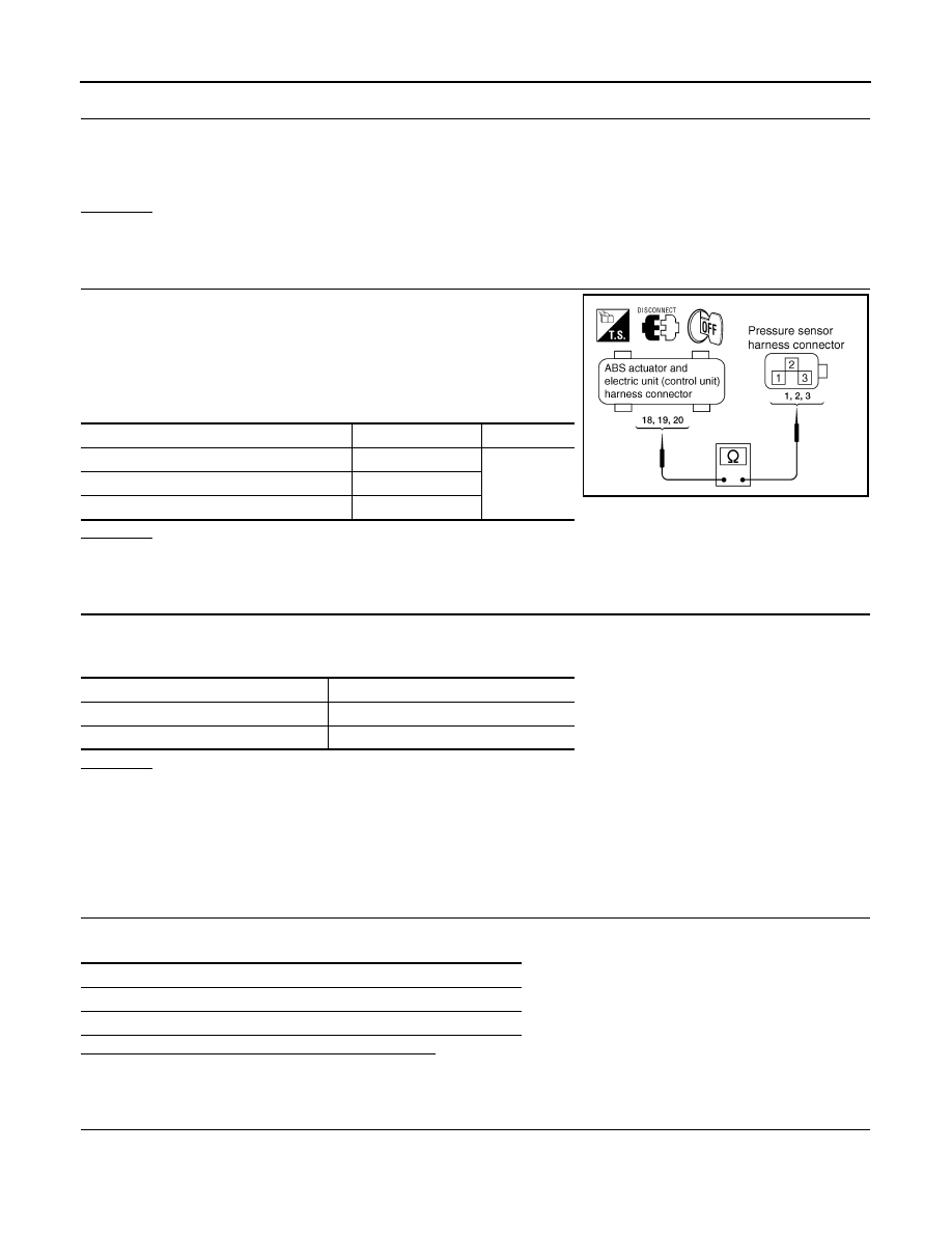
6.
CHECK PRESSURE SENSOR HARNESS
1.
Turn ignition switch OFF and disconnect pressure sensor con-
nector E53 and ABS actuator and electric unit (control unit) con-
nector E56.
2.
Check continuity between ABS actuator and electric unit (control
unit) harness connector and pressure sensor harness connec-
tor.
OK or NG
OK
>> GO TO 7.
NG
>> If the open or short in harness, repair or replace harness.
7.
CHECK PRESSURE SENSOR
1.
Connect pressure sensor connector and ABS actuator and electric unit (control unit) connector.
2.
Perform “DATA MONITOR” of the “PRESS SENSOR” to check if the status is normal.
OK or NG
OK
>> INSPECTION END
NG
>> Pressure sensor is damaged or malfunctioning, replace pressure sensor.
DTC C1143 ST ANG SEN CIRCUIT
INFOID:0000000001327681
INSPECTION PROCEDURE
1.
CHECK SELF-DIAGNOSTIC RESULTS
Check the self-diagnostic results.
Is the above displayed in the self-diagnosis item?
YES
>> GO TO 2.
NO
>> INSPECTION END
2.
CHECK CONNECTOR
1.
Disconnect steering angle sensor connector and ABS actuator and electric unit (control unit) connector
and check terminals for deformation, disconnection, looseness, and so on. If any malfunction is found,
repair or replace terminal.
ABS actuator and electric unit (control unit)
Pressure sensor
Continuity
19
1
Yes
20
2
18
3
SFIA1188E
Condition
Data monitor display
When brake pedal is depressed.
0 to 170 bar
When brake pedal is released.
Approx. 0 bar
Self-diagnostic results
ST ANG SEN CIRCUIT
ST ANG SEN COM CIR
TROUBLE DIAGNOSIS FOR SYSTEM
BRC-45
< SERVICE INFORMATION >
[VDC/TCS/ABS]
C
D
E
G
H
I
J
K
L
M
A
B
BRC
N
O
P
2.
Reconnect connectors and perform an ABS actuator and electric unit (control unit) self-diagnosis again.
OK or NG
OK
>> Connector terminal contact is loose, damaged, open or shorted.
NG
>> GO TO 3.
3.
CHECK STEERING ANGLE SENSOR HARNESS
1.
Check CAN communication circuit. Refer to
BRC-48, "DTC U1000 CAN COMM CIRCUIT"
.
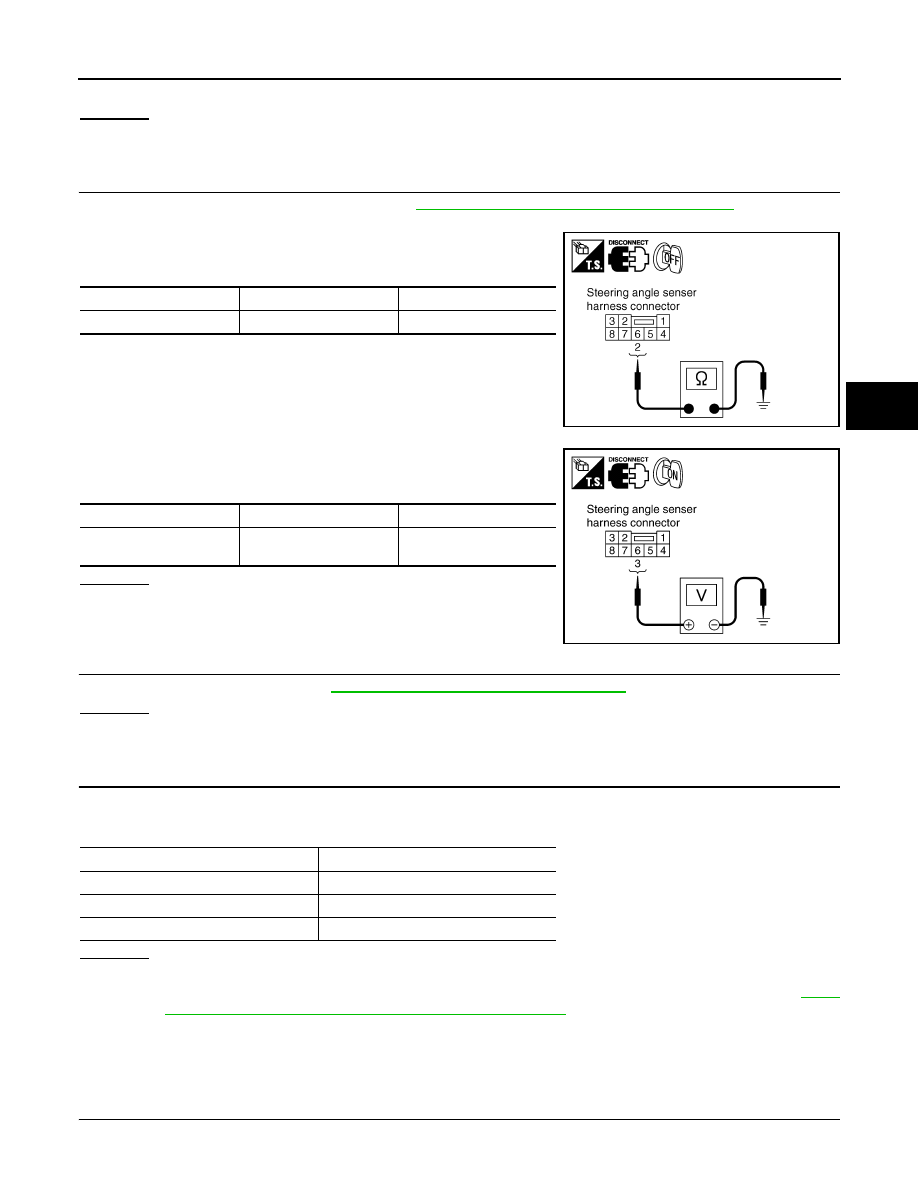
2.
Turn ignition switch OFF and disconnect steering angle sensor connector M14.
3.
Check continuity between steering angle sensor harness con-
nector and ground.
4.
Check voltage between steering angle sensor harness connec-
tor and ground.
OK or NG
OK
>> GO TO 4.
NG
>> If the open or short in harness, repair or replace har-
ness.
4.
CHECK STEERING WHEEL PLAY
Check steering wheel play. Refer to
PS-9, "On-Vehicle Inspection and Service"
OK or NG
OK
>> GO TO 5
NG
>> Adjust steering wheel play.
5.
PERFORM DATA MONITOR
1.
Connect steering angle sensor and ABS actuator and electric unit (control unit) connectors.
2.
Perform “DATA MONITOR” of the “STEERING ANGLE SIGNAL” to check if the status is normal.
OK or NG
OK
>> Perform ABS actuator and electric unit (control unit) self-diagnosis again.
NG
>> Replace steering angle sensor and adjust neutral position of steering angle sensor. Refer to
8, "Adjustment of Steering Angle Sensor Neutral Position"
DTC C1144 ST ANG SEN SIGNAL
INFOID:0000000001327688
INSPECTION PROCEDURE
1.
CHECK SELF-DIAGNOSTIC RESULTS (1)
Check self-diagnostic results.
Steering angle sensor
Ground
Continuity
2
—
Yes
SFIA1189E
Steering angle sensor
Ground
Voltage
3
—
Battery voltage
(Approx. 12 V)
SFIA1190E
Steering condition
Data monitor display
Straight-ahead
-3.5 deg - +3.5 deg
Turn wheel to the right by 90
°
.
Approx. -90 deg
Turn wheel to the left by 90
°
.
Approx. +90 deg
Нет комментариевНе стесняйтесь поделиться с нами вашим ценным мнением.
Текст