Infiniti FX35 / FX45. Manual — part 879
REAR DRIVE SHAFT
RAX-15
< SERVICE INFORMATION >
C
E
F
G
H
I
J
K
L
M
A
B
RAX
N
O
P
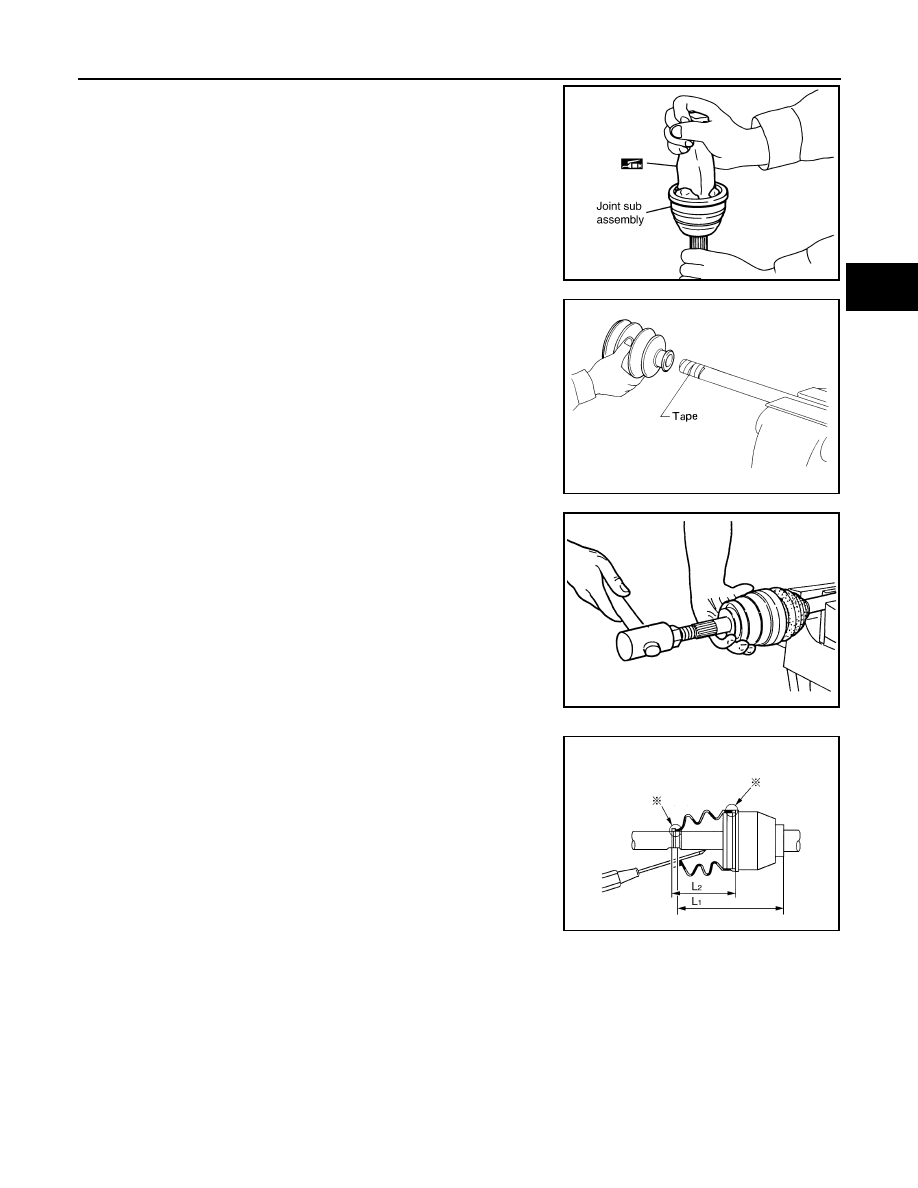
1.
Insert the amount of grease (NISSAN genuine grease or equiva-
lent) into joint sub-assembly serration hole until grease begins to
ooze from ball groove and serration hole. After insert grease,
use a shop cloth to wipe off old grease that has oozed out.
2.
Wind serrated part of shaft with tape. Install boot band and boot
to shaft. Be careful not to damage boot.
NOTE:
Discard old boot band and boot; replace with each new one.
3.
Remove protective tape wound around serrated part of shaft.
4.
Attach circular clip to shaft. At this time, circular clip must fit
securely into shaft groove. Attach nut to joint sub-assembly.
Use a wooden hammer to press-fit.
NOTE:
Discard old circular clip; replace with new one.
5.
Insert the amount of grease (NISSAN genuine grease or equiva-
lent) listed below into housing from large end of boot.
6.
Install boot securely into grooves (indicated by * marks) shown
in the figure.
CAUTION:
If there is grease on boot mounting surfaces (indicated by *
marks) of shaft and housing, boot may come off. Remove
all grease from surfaces.
7.
Make sure boot installation length “L” is the length indicated
below. Insert a flat-bladed screwdriver or similar tool into smaller
side of boot. Bleed air from boot to prevent boot deformation.
CAUTION:
• Boot may break if boot installation length is less than standard value.
• Be careful that screwdriver tip does not contact inside surface of boot.
SDIA1127E
SFA800
Grease amount
VK45DE
: 140
−
160 g (4.93
−
5.64 oz)
VQ35DE
: 86
−
96 g (3.03
−
3.38 oz)
RAC0049D
Boot installation length “L”
L
1 (
VK45DE)
: 141.5 mm (5.57 in)
L
2 (
VQ35DE)
: 97 mm (3.82 in)
JPDIG0020ZZ
RAX-16
< SERVICE INFORMATION >
REAR DRIVE SHAFT
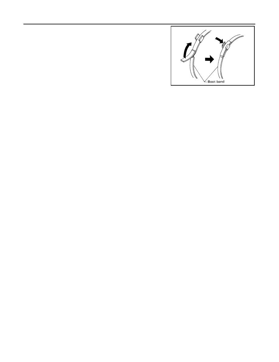
8.
Secure big and small ends of boot with new boot bands as
shown in the figure.
NOTE:
Discard old boot bands; replace with new ones.
9.
After installing joint sub-assembly and shaft, rotate boot to check
whether or not the actual position is correct. If boot position is
not correct, secure boot with new boot bands again.
SFA395
SERVICE DATA AND SPECIFICATIONS (SDS)
RAX-17
< SERVICE INFORMATION >
C
E
F
G
H
I
J
K
L
M
A
B
RAX
N
O
P
SERVICE DATA AND SPECIFICATIONS (SDS)
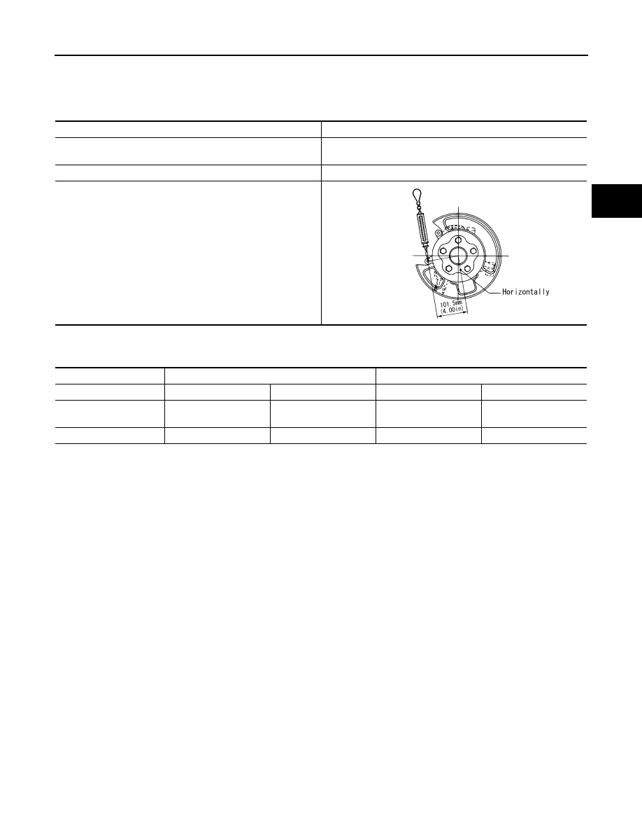
Wheel Bearing
INFOID:0000000001327531
Drive Shaft
INFOID:0000000001327532
Axial end play
0.05 mm (0.002 in) or less
Rotational torque
At a load of 49,033 N (5,000 kg, 11,000 lb)
Less than 2.7 N·m (0.28 kg-m, 24 in-lb)
Measurement of spring scale
Less than 26.6 N (2.7 kg, 5.95 lb)
Measuring point (Brake caliper installation points)
SDIA0801E
Joint
Wheel side
Final drive side
Engine model
VQ35DE
VK45DE
VQ35DE
VK45DE
Grease quantity
86
−
96 g
(3.03
−
3.38 oz)
140
−
160 g
(4.93
−
5.64 oz)
124
−
134 g
(4.37
−
4.72 oz)
175
−
195 g
(6.17
−
6.87 oz)
Boots installed length
97 mm (3.82 in)
141.5 mm (5.57 in)
93.9 mm (3.697 in)
147.9 mm (5.82 in)
RF-1
BODY
C
D
E
F
G
H
J
K
L
M
SECTION
RF
A
B
RF
N
O
P
CONTENTS
ROOF
SERVICE INFORMATION . . . . . . .
PRECAUTIONS . . . . . . . . . . . . ...
Precaution . . . . . . . . . . . . . . . .....
PREPARATION . . . . . . . . . . . . ...
Special Service Tool . . . . . . . . . . . .....
Commercial Service Tool . . . . . . . . . . ..
SQUEAK AND RATTLE TROUBLE DIAG-
NOSES . . . . . . . . . . . . . . . .
Work Flow . . . . . . . . . . . . . . . .....
Generic Squeak and Rattle Troubleshooting . . ....
Diagnostic Worksheet . . . . . . . . . . . ...
SUNROOF . . . . . . . . . . . . . . ..
Component Parts and Harness Connector Loca-
tion . . . . . . . . . . . . . . . . . . ..
System Description . . . . . . . . . . . . ..
CAN Communication System Description . . . ...
CAN Communication Unit . . . . . . . . . .
Wiring Diagram - SROOF - . . . . . . . . . ..
Terminal and Reference Value for BCM . . . . ..
Terminal and Reference Value for Sunroof Motor
Assembly . . . . . . . . . . . . . . . . .
Work Flow . . . . . . . . . . . . . . . .
CONSULT-III Function (BCM) . . . . . . . . .
Trouble Diagnosis Chart by Symptom . . . . . .
Check BCM Power Supply and Ground Circuit . ...
Check Sunroof Motor Assembly Power Supply
and Ground Circuit . . . . . . . . . . . . ..
Check Sunroof Switch System . . . . . . . .
Check Door Switch . . . . . . . . . . . . ..
Wind Deflector Inspection . . . . . . . . . .
Link and Wire Assembly . . . . . . . . . . ..
Fitting Adjustment . . . . . . . . . . . . .
Нет комментариевНе стесняйтесь поделиться с нами вашим ценным мнением.
Текст