Infiniti FX35 / FX45. Manual — part 877

REAR WHEEL HUB AND KNUCKLE
RAX-7
< SERVICE INFORMATION >
C
E
F
G
H
I
J
K
L
M
A
B
RAX
N
O
P
9.
Remove parking brake cable and parking brake shoe from back plate. Refer to
.
10. Remove fixing nuts of anchor block with power tool, then remove anchor block and back plate from axle.
11. Loosen fixing bolts and nuts of front lower link, radius rod, and rear lower link in side of suspension mem-
ber.
12. Set jack under rear lower link. Then remove fixing bolt in front lower link side of shock absorber with
power tool.
13. Remove bolt and nut in axle side of rear lower link with power tool. Then remove coil spring. Refer to
14. Remove fixing bolts and nuts in axle side of front lower link, radius rod with power tool.
15. Remove suspension arm and cotter pin at axle, then loosen mounting nut.
16. Use a ball joint remover (suitable tool) to remove suspension arm from axle. Be careful not to damage ball
joint boot.
CAUTION:
Tighten temporarily mounting nut to prevent damage to threads and to prevent ball joint remover
(suitable tool) from coming off.
17. Remove axle from vehicle.
INSPECTION AFTER REMOVAL
Check for deformity, cracks and damage on each parts, replace if necessary.
Ball Joint Inspection
Check for boot breakage, axial looseness, and torque of suspension arm ball joint. Refer to
.
INSTALLATION
• Refer to "Removal and Installation" for tightening torque. Install in the reverse order of removal.
NOTE:
Refer to component parts location and do not reuse non-reusable parts.
• Perform final tightening of installation position of suspension links (rubber bushing) under unladen conditions
with tires on level ground, Check wheel alignment. Refer to
RSU-5, "Wheel AlignmentInspection"
• After adjusting wheel alignment, adjust neutral position of steering angle sensor. Refer to
ment of Steering Angle Sensor Neutral Position"
Disassembly and Assembly
INFOID:0000000001327528
DISASSEMBLY
Wheel Bearing
CAUTION:
Do not disassemble if wheel bearing has no trouble.
1.
Remove wheel bearing fixing bolts and anchor block fixing nuts, and remove wheel hub and bearing
assembly, back plate and anchor block from axle.
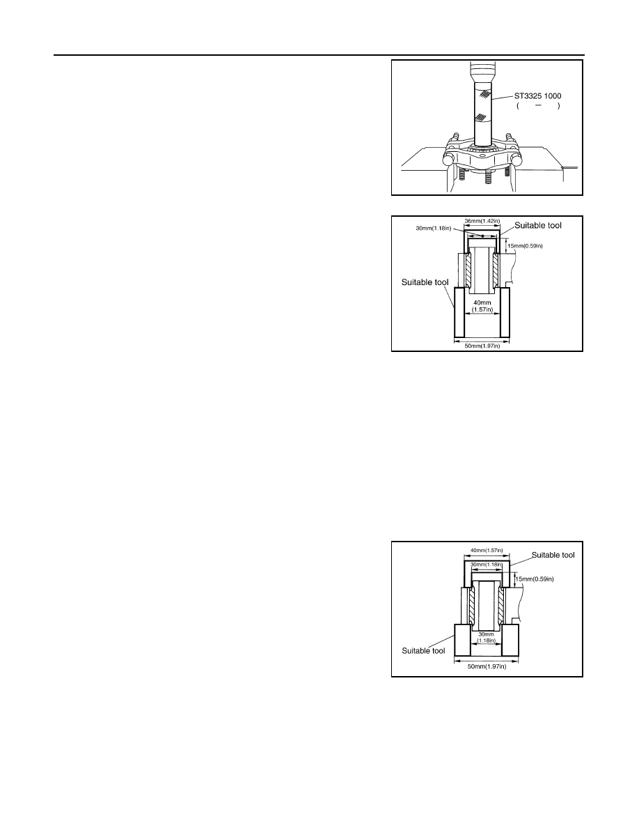
2.
Using a drift (SST) and a puller (suitable tool), press wheel hub
out to remove from wheel bearing.
SDIA1482E
RAX-8
< SERVICE INFORMATION >
REAR WHEEL HUB AND KNUCKLE
3.
Using a drift (SST) and a puller (suitable tool), press wheel bear-
ing outer side inner race out to remove from wheel hub.
Bushing
Using a suitable drift, remove each bushing from axle.
INSPECTION AFTER DISASSEMBLY
Check for deformity, cracks and damage of each parts, replace if necessary.
Wheel Hub
Inspect wheel hub for deformation, cracks, and other damage. If any irregular conditions are found, replace
wheel hub.
Axle
Inspect axle for deformation, cracks, and other damage. If any irregular conditions are found, replace axle.
Back Plate
Inspect back plate for deformation, cracks, and other damage. If any irregular conditions are found, replace
back plate.
ASSEMBLY
Bushing
Using a suitable drift to install each bushing onto axle.
Wheel Bearing
SDIA1483E
SDIA1484E
SDIA1485E
REAR WHEEL HUB AND KNUCKLE
RAX-9
< SERVICE INFORMATION >
C
E
F
G
H
I
J
K
L
M
A
B
RAX
N
O
P
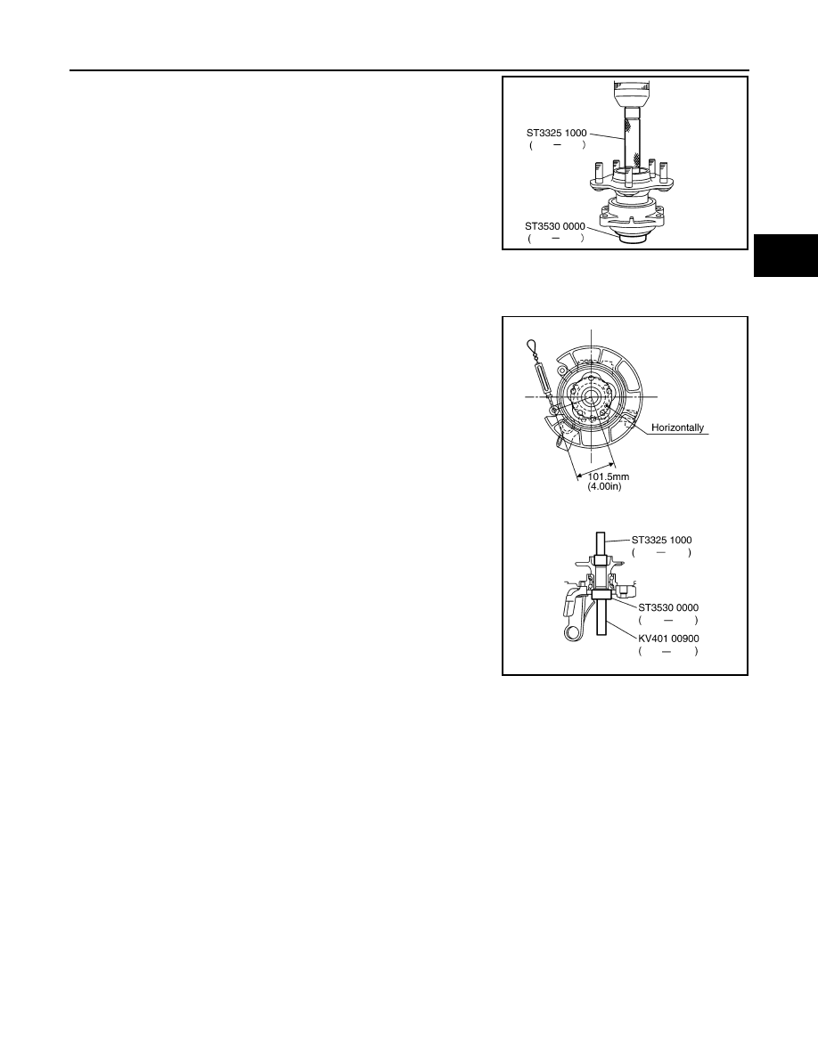
1.
Press fit a wheel hub into wheel bearing with a drift (SST).
CAUTION:
• Press fit a drift (SST) while holding it against wheel bear-
ing inner side inner race.
• Wheel bearing cannot be reused. Do not attempt to reuse
it.
NOTE:
Final press load guideline 49,033 N (5,000 kg, 11,000 lb)
2.
Install back plate and wheel hub and bearing assembly.
3.
Install anchor block onto axle.
INSPECTION AFTER ASSEMBLY
1.
With wheel bearing pressed into axle housing, apply 49,033 N (5,000 kg, 11,000 lb) to wheel hub and
rotate both clockwise and counterclockwise 10 times to minimize resistance.
2.
Attach spring scale in the position shown in illustration and pull
at a rate of 10
±
2 rpm to measure rotating torque.
SDIA1120E
Rotating torque:
Less than 2.7 N·m (0.28 kg-m, 24 in-lb)
Spring scale reading:
Less than 26.6 N (2.7 kg, 5.97 lb)
SDIA1486E
RAX-10
< SERVICE INFORMATION >
REAR DRIVE SHAFT
REAR DRIVE SHAFT
Removal and Installation
INFOID:0000000001327529
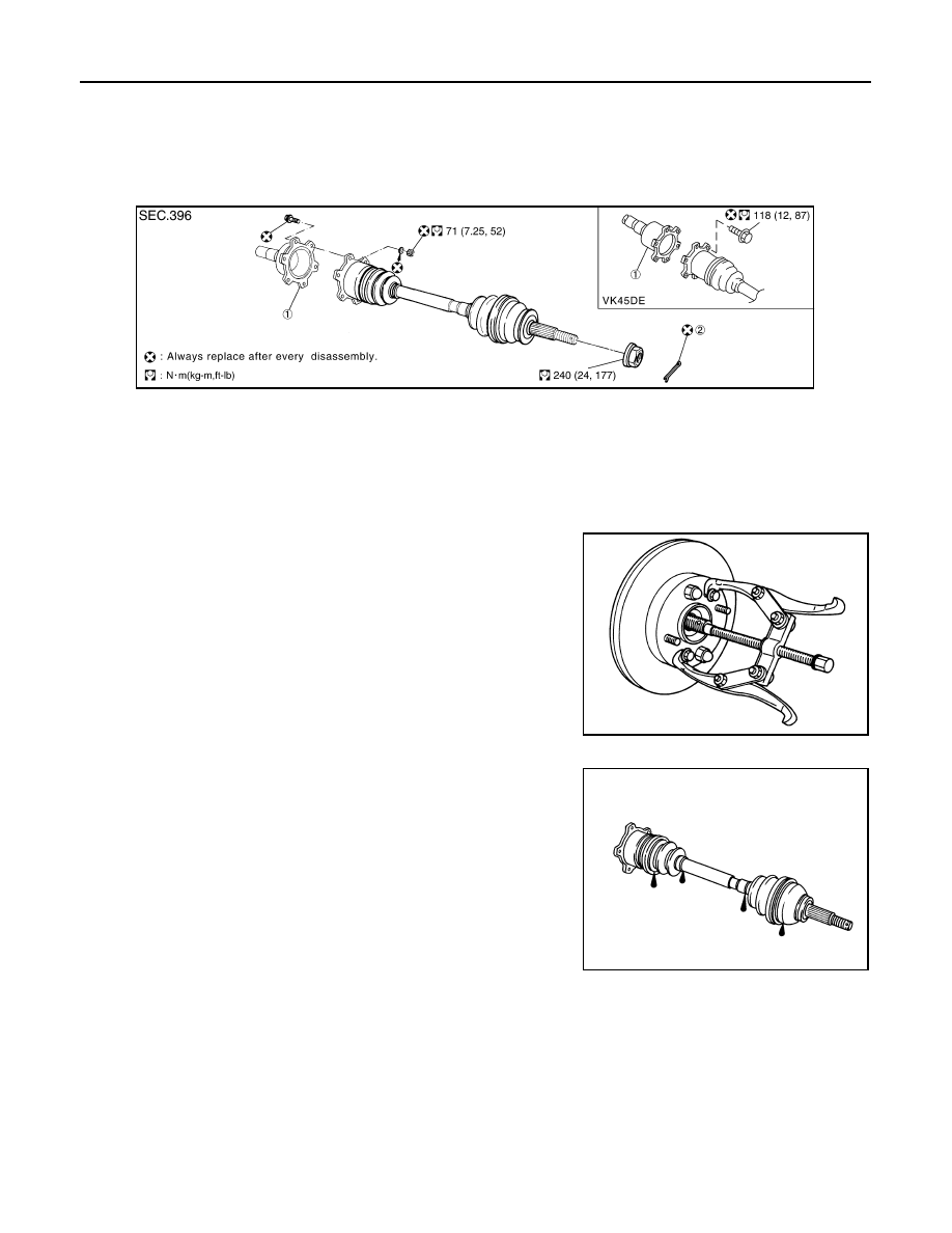
COMPONENTS
REMOVAL
1.
Remove tires from vehicle with power tool.
2.
Remove cotter pin. Then remove lock nut from drive shaft.
3.
Remove fixing nuts and bolts between side flange and drive shaft with power tool.
4.
Using a puller (suitable tool), remove drive shaft from steering
knuckle.
CAUTION:
When removing drive shaft, do not apply an excessive
angle to drive shaft joint.Also be careful not to excessively
extend slide joint.
5.
Remove drive shaft from axle.
INSPECTION AFTER REMOVAL
• Move joint up/down, left/right, and in the axial direction. Check for
any rough movement or significant looseness.
• Check boot for cracks or other damage, and also for grease leak-
age.
• If a trouble is found, disassemble drive shaft, and then replace with
new one.
INSTALLATION
Refer to "Removal and Installation" for tightening torque. Install in the reverse order of removal.
NOTE:
Refer to component parts location and do not reuse non-reusable parts.
Disassembly and Assembly
INFOID:0000000001327530
COMPONENTS
1.
Side flange
2.
Cotter pin
SDIA1487E
SDIA0972J
RAA0030D
Нет комментариевНе стесняйтесь поделиться с нами вашим ценным мнением.
Текст