Infiniti FX35 / FX45. Manual — part 878
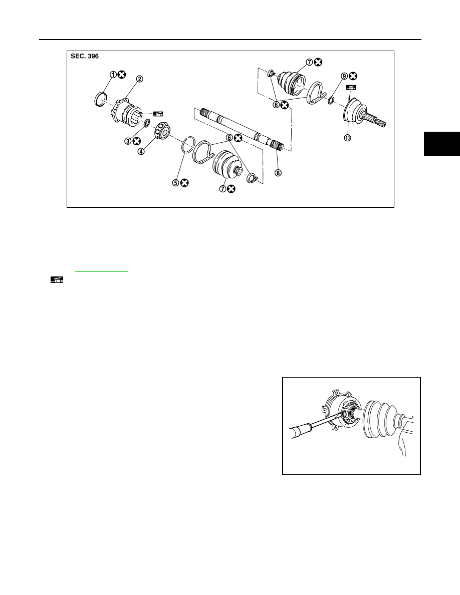
REAR DRIVE SHAFT
RAX-11
< SERVICE INFORMATION >
C
E
F
G
H
I
J
K
L
M
A
B
RAX
N
O
P
DISASSEMBLY
Final Drive Side
1.
Press shaft in a vice.
CAUTION:
When retaining drive shaft in a vise, always use copper or aluminum plates between vise and
shaft.
2.
Remove boot bands.
3.
If plug needs to be removed, move boot to wheel side, and drive it out with a plastic hammer.
4.
Remove stopper ring with a flat-bladed screwdriver, and pull out
housing.
1.
Plug
2.
Housing
3.
Snap ring
4.
Ball cage/Steel ball/Inner race as-
sembly
5.
Stopper ring
6.
Boot band
7.
Boot
8.
Shaft
9.
Circular clip
10. Joint sub-assembly
Refer to
, for the symbols in the figure.
: Apply Nissan genuine grease or equivalent.
PDIA1229E
SRA249A
RAX-12
< SERVICE INFORMATION >
REAR DRIVE SHAFT
5.
Remove snap ring, then remove ball cage/steel ball/inner race
assembly from shaft.
6.
Remove boot from shaft.
7.
Remove old grease on housing with paper towels.
Wheel Side
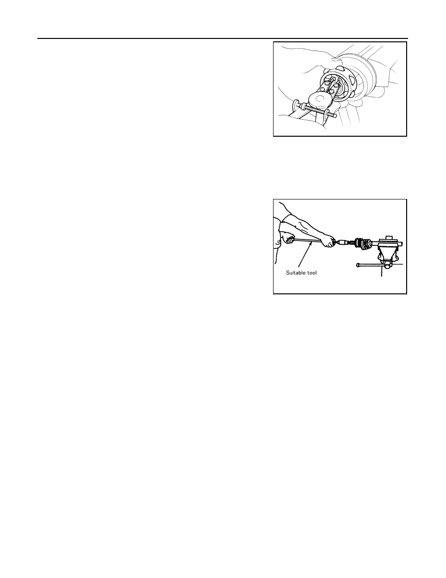
1.
Place shaft in a vice.
CAUTION:
When retaining drive shaft in a vise, always use copper or aluminum plates between vise and
shaft.
2.
Remove boot bands. Then remove boot from joint sub-assembly.
3.
Screw a drive shaft puller 30 mm (1.18 in) or more into threaded
part of joint sub-assembly. Pull joint sub-assembly out of shaft.
CAUTION:
• If joint sub-assembly cannot be removed after five or
more unsuccessful attempts, replace shaft and joint sub-
assembly as a set.
• Align sliding hammer and drive shaft and remove them by
pulling directly.
4.
Remove boot from shaft.
5.
Remove circular clip from shaft.
6.
While rotating ball cage, remove old grease on joint sub-assem-
bly with paper towels.
INSPECTION AFTER DISASSEMBLY
Shaft
Replace shaft if there is any runout, cracking, or other damage.
Joint Sub-Assembly
• Make sure there is no rough rotation or unusual axial looseness.
• Make sure there is no foreign material inside joint.
• Check joint sub-assembly for compression scars, cracks, or fractures.
CAUTION:
If there are any irregular conditions of joint sub-assembly components, replace the entire joint sub-
assembly.
Sliding Joint Side (Housing)
• Make sure there are no compression scars, cracks, fractures or unusual wear of ball rolling surface.
• Make sure there is no damage to shaft screws.
• Make sure there is no deformation of boot installation parts.
Ball Cage
Make sure there are no compression scars, cracks, fractures of sliding surface.
Steel Ball
Make sure there are no compression scars, cracks, fractures or unusual wear.
Inner Race
• Check ball sliding surface for compression scars, cracks, or fractures.
• Make sure there is no damage to serrated part.
CAUTION:
If there are any irregular conditions in the component, replace with a new set of housing, ball cage,
steel ball and inner race.
ASSEMBLY
SFA514A
SDIA0606E
REAR DRIVE SHAFT
RAX-13
< SERVICE INFORMATION >
C
E
F
G
H
I
J
K
L
M
A
B
RAX
N
O
P
Final Drive Side
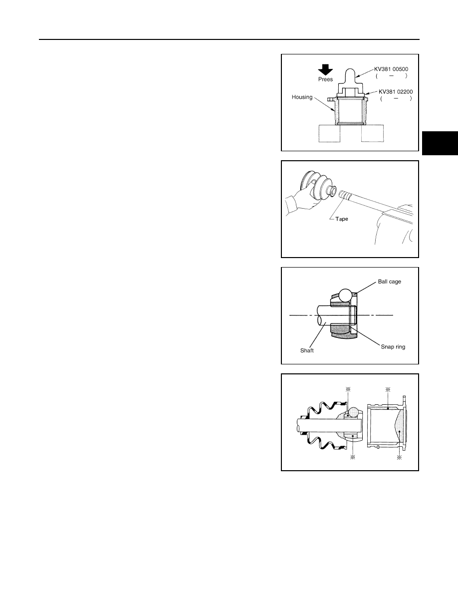
1.
If plug has been removed, use a drift (SST) to press in a new
one.
NOTE:
Discard old plug; replace with new one.
2.
Wind serrated part of shaft with tape. Install boot band and boot
to shaft. Be careful not to damage boot.
NOTE:
Discard old boot band and boot; replace with each new one.
3.
Remove protective tape wound around serrated part of shaft.
4.
Install ball cage/steel ball/inner race assembly to shaft, and
secure them tightly with a snap ring.
NOTE:
Discard old snap ring; replace with new one.
5.
Insert the amount of grease (NISSAN genuine grease or equiva-
lent) onto housing (* point) to the quantity mentioned below, and
install it to shaft.
6.
Install stopper ring to housing.
7.
After installed, pull shaft to check engagement between joint
sub-assembly and stopper ring.
SDIA1153E
SFA800
SDIA1125E
Grease amount
VK45DE
: 175
−
195 g (6.17
−
6.87 oz)
VQ35DE
: 124
−
134 g (4.37
−
4.72 oz)
RAC0678D

RAX-14
< SERVICE INFORMATION >
REAR DRIVE SHAFT
8.
Install boot securely into grooves (indicated by * marks) shown
in the figure.
CAUTION:
If there is grease on boot mounting surfaces (indicated by *
marks) of shaft and housing, boot may come off. Remove
all grease from surfaces.
9.
Make sure boot installation length “L” is the length indicated
below. Insert a flat-bladed screwdriver or similar tool into smaller
side of boot. Bleed air from boot to prevent boot deformation.
CAUTION:
• Boot may break if boot installation length is less than standard value.
• Take care not to touch the tip of screwdriver to inside of boot.
10. Secure big and small ends of boot with new boot bands as
shown in the figure. (VK45DE)
NOTE:
Discard old boot bands; replace with new ones.
11. Secure big and small ends of boot with new boot bands. (VQ35DE)
NOTE:
Discard old boot bands; replace with new ones.
a.
Put boot band in the groove on drive shaft boot. Then fit pawls
(
) into holes to temporary installation.
NOTE:
For the large diameter side, fit projection (A) and guide slit (B) at
first.
b.
Pinch projection on the band with suitable pliers to tighten band.
c.
Insert tip of band below end of the pawl.
12. After installing housing and shaft, rotate boot to check whether
or not the actual position is correct. If boot position is not correct,
secure boot with new boot band again.
Wheel Side
Boot installation Length “L”
VK45DE
: 147.9 mm (5.82 in)
VQ35DE
: 93.9 mm (3.697 in)
SDIA1738E
SFA395
SDIA3557E
SDIA3558E
Нет комментариевНе стесняйтесь поделиться с нами вашим ценным мнением.
Текст