Infiniti FX35 / FX45. Manual — part 792
HEADLAMP AIMING CONTROL
LT-63
< SERVICE INFORMATION >
C
D
E
F
G
H
I
J
L
M
A
B
LT
N
O
P
TKWM4301E
LT-64
< SERVICE INFORMATION >
HEADLAMP AIMING CONTROL
Removal and Installation
INFOID:0000000001328325
REMOVAL
TKWM4302E
HEADLAMP AIMING CONTROL
LT-65
< SERVICE INFORMATION >
C
D
E
F
G
H
I
J
L
M
A
B
LT
N
O
P
1.
Remove combination meter. Refer to
Installation of Combination Meter"
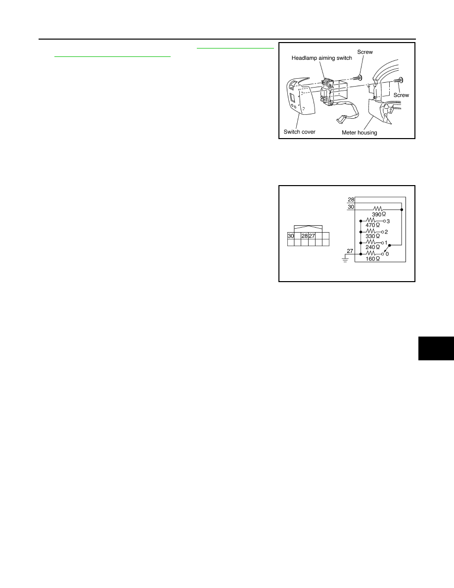
2.
Remove screws for removing headlamp aiming switch from
meter housing.
3.
Remove screws and then remove headlamp aiming switch.
INSTALLATION
Installation is the reverse order of removal.
Switch Circuit Inspection
INFOID:0000000001328326
Using a circuit tester, check resistance between the headlamp aim-
ing switch connector terminals in each operation status of the aiming
switch.
PKIB3630E
PKIC1215E
LT-66
< SERVICE INFORMATION >
FRONT FOG LAMP
FRONT FOG LAMP
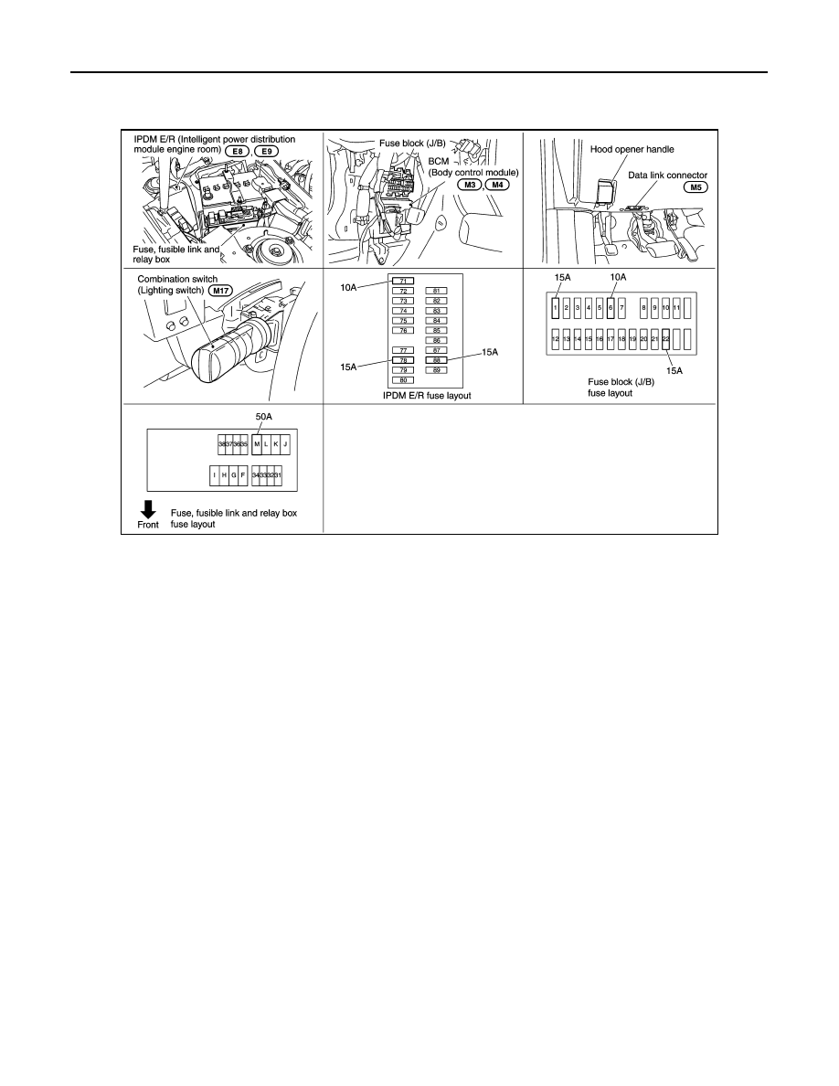
Component Parts and Harness Connector Location
INFOID:0000000001328327
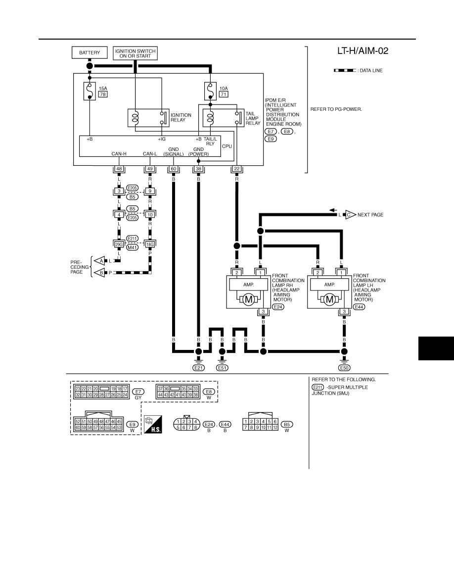
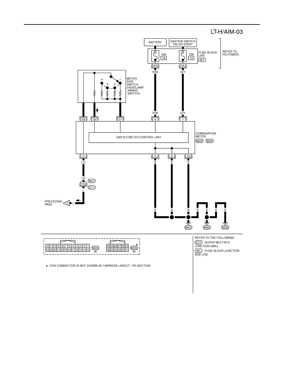
System Description
INFOID:0000000001328328
Control of the front fog lamps is dependent upon the position of the combination switch (lighting switch). The
lighting switch must be in the 2ND position or AUTO position (headlamp is ON) for front fog lamp opera-
tion.When the lighting switch is placed in the front fog lamp on position the BCM (body control module)
receives input signal requesting the front fog lamps to illuminate. When the headlamps are illuminated, this
input signal is communicated to the IPDM E/R (intelligent power distribution module engine room) through the
CAN communication lines. The CPU (central processing unit) located in the IPDM E/R controls the front fog
lamp relay coil. When activated, this relay directs power to the front fog lamps.
OUTLINE
Power is supplied at all times
• to ignition relay, located in IPDM E/R, from battery direct,
• through 15A fuse (No. 88, located in IPDM E/R)
• to front fog lamp relay, located in IPDM E/R,
• through 15A fuse (No. 78, located in IPDM E/R)
• to CPU located in IPDM E/R,
• through 10A fuse (No. 71, located in IPDM E/R)
• to CPU located in IPDM E/R.
• through 50A fusible link (letter M, located in fuse, fusible link and relay box)
• to BCM terminal 55,
• through 15A fuse [No. 22, located in fuse block (J/B)]
• to BCM terminal 42.
When ignition switch is in ON or START position, power is supplied
• to ignition relay (located IPDM E/R)
• through 15A fuse [No. 1, located in fuse block (J/B)]
• to BCM terminal 38.
When ignition switch is in ACC or ON position, power is supplied
• through 10A fuse [No. 6, located in fuse block (J/B)]
• to BCM terminal 11.
Ground is supplied
PKIB3475E
Нет комментариевНе стесняйтесь поделиться с нами вашим ценным мнением.
Текст