Infiniti FX35 / FX45. Manual — part 791
AUTO LIGHT SYSTEM
LT-59
< SERVICE INFORMATION >
C
D
E
F
G
H
I
J
L
M
A
B
LT
N
O
P
Optical sensor System Inspection
INFOID:0000000001381750
1.
CHECK OPTICAL SENSOR INPUT SIGNAL
CONSULT-III DATA MONITOR
1.
Turn ignition switch ON.
2.
Select “OPTICAL SENSOR” of BCM (HEAD LAMP) data monitor item.
3.
Turn the lighting switch AUTO.
4.
With the optical sensor illuminating, check the monitor status.
CAUTION:
Optical sensor must be securely subjected to work lamp light. If optical sensor is insufficiently illumi-
nated, the measured value may not satisfy the standard.
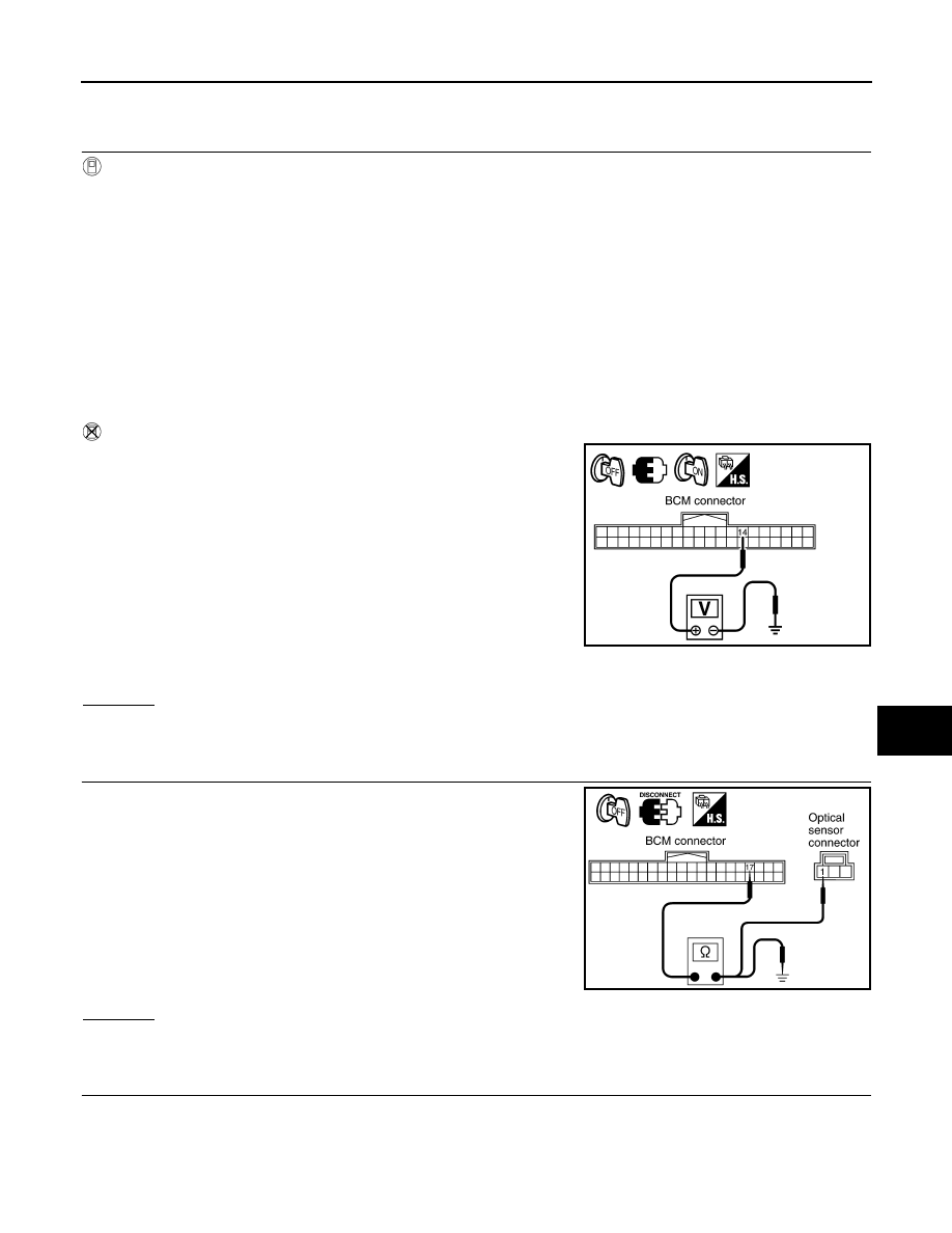
CHECK BCM
1.
Turn ignition switch ON.
2.
Check voltage between BCM harness connector M3 terminal 14
and ground.
CAUTION:
Optical sensor must be securely subjected to work lamp light. If
optical sensor is insufficiently illuminated, the measured value
may not satisfy the standard.
OK or NG
OK
>> INSPECTION END
NG
>> GO TO 2.
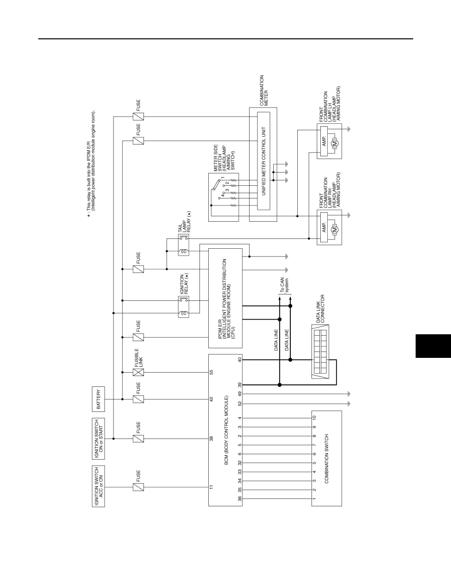
2.
CHECK OPTICAL SENSOR POWER SUPPLY CIRCUIT
1.
Turn ignition switch OFF.
2.
Disconnect BCM connector and optical sensor connector.
3.
Check continuity (open circuit) between BCM harness connector
M3 terminal 17 and optical sensor harness connector M37 ter-
minal 1.
4.
Check continuity (short circuit) between BCM harness connector
M3 terminal 17 and ground.
OK or NG
OK
>> GO TO 3.
NG
>> Repair harness or connector.
3.
CHECK OPTICAL SENSOR SIGNAL CIRCUIT
Illuminated
OPTICAL SENSOR
: 3.1 V or more
Not illuminated
OPTICAL SENSOR
: 0.6 V or less
Illuminated
OPTICAL SENSOR
: 3.1 V or more
Not illuminated
OPTICAL SENSOR
: 0.6 V or less
PKIB6163E
17 – 1
: Continuity should exist.
17 – Ground
: Continuity should not exist.
SKIA5891E

LT-60
< SERVICE INFORMATION >
AUTO LIGHT SYSTEM
1.
Check continuity (open circuit) between BCM harness connector
M3 terminal 14 and optical sensor harness connector M37 ter-
minal 2.
2.
Check continuity (short circuit) between BCM harness connector
M3 terminal 14 and ground.
OK or NG
OK
>> GO TO 4.
NG
>> Repair harness or connector.
4.
CHECK OPTICAL SENSOR GROUND CIRCUIT
1.
Check continuity (open circuit) between BCM harness connector
M3 terminal 18 and optical sensor harness connector M37 ter-
minal 3.
2.
Check continuity (short circuit) between BCM harness connector
M3 terminal 18 and ground.
OK or NG
OK
>> GO TO 5.
NG
>> Repair harness or connector.
5.
CHECK OPTICAL SENSOR VOLTAGE
1.
Connect BCM connector.
2.
Turn ignition switch ON.
3.
Check voltage between BCM harness connector M3 terminal 17
and ground.
OK or NG
OK
>> Replace optical sensor.
NG
BCS-13, "Removal and Installa-
Removal and Installation of Optical Sensor
INFOID:0000000001328322
REMOVAL
1.
Insert a screwdriver or similar tool and remove front defroster
grill (LH). Refer to
IP-11, "Removal and Installation"
.
2.
Disconnect optical sensor connector.
3.
Remove optical sensor.
INSTALLATION
Installation is the reverse order of removal.
14 – 2
: Continuity should exist.
14 – Ground
: Continuity should not exist.
SKIA5892E
18 – 3
: Continuity should exist.
18 – Ground
: Continuity should not exist.
SKIA5893E
17 – Ground
: Approx. 5 V
SKIA5894E
PKIA5275E
HEADLAMP AIMING CONTROL
LT-61
< SERVICE INFORMATION >
C
D
E
F
G
H
I
J
L
M
A
B
LT
N
O
P
HEADLAMP AIMING CONTROL
Schematic
INFOID:0000000001328323
TKWH0337E

LT-62
< SERVICE INFORMATION >
HEADLAMP AIMING CONTROL
Wiring Diagram - H/AIM -
INFOID:0000000001328324
TKWM4300E
Нет комментариевНе стесняйтесь поделиться с нами вашим ценным мнением.
Текст