Infiniti FX35 / FX45. Manual — part 115

ATC-56
< SERVICE INFORMATION >
TROUBLE DIAGNOSIS
3.
Check continuity between each door motor harness connector
terminal 2 and ground.
OK or NG
OK
>> GO TO 6.
NG
>> Repair harness or connector.
6.
CHECK MOTOR OPERATION
1.
Reconnect each door motor connector.
2.
Turn ignition switch ON.
3.
Confirm operation of each door motor.
OK or NG
OK
>>
(Return to operate normally.)
• Poor contact in motor connector.
NG
>>
(Does not operate normally.)
• GO TO 7.
7.
CHECK AIR MIX DOOR MOTOR AND INTAKE DOOR MOTOR OPERATION
1.
Turn ignition switch OFF.
2.
Disconnect mode, air mix (driver side, passenger side), and intake door motor connectors.
3.
Reconnect air mix (driver side, passenger side) and intake door motor connectors.
4.
Turn ignition switch ON.
5.
Confirm operation of air mix door motor (driver side, passenger side) and intake door motor.
OK or NG
OK
>>
[Air mix (driver side, passenger side) and intake door motors operate normally.]
• Replace mode door motor.
NG
>>
[Air mix (driver side, passenger side) and intake door motors does not operate normally.]
• GO TO 8.
8.
CHECK MODE DOOR MOTOR AND INTAKE DOOR MOTOR OPERATION
1.
Turn ignition switch OFF.
2.
Disconnect air mix door motor (driver side, passenger side) connectors.
3.
Reconnect mode door motor connector.
4.
Turn ignition switch ON.
5.
Confirm operation of mode door motor and intake door motor.
OK or NG
OK
>>
(Mode and intake door motors operate normally.)
• GO TO 10.
NG
>>
(Mode and intake door motors does not operate normally.)
• GO TO 9.
9.
CHECK MODE DOOR MOTOR AND AIR MIX DOOR MOTOR OPERATION
1.
Turn ignition switch OFF.
2.
Disconnect intake door motor connector.
3.
Reconnect air mix door motor (driver side, passenger side) connectors.
4.
Turn ignition switch ON.
5.
Confirm operation of mode door motor and air mix door motor (driver side, passenger side).
OK or NG
OK
>>
[Mode and air mix door motor (driver side, passenger side) operate normally.]
• Replace intake door motor.
NG
>>
[Mode and air mix door motor (driver side, passenger side) does not operate normally.]
• Replace display and A/C auto amp.
10.
CHECK AIR MIX DOOR MOTOR OPERATION
2 – Ground
: Continuity should exist.
RJIA1990E
TROUBLE DIAGNOSIS
ATC-57
< SERVICE INFORMATION >
C
D
E
F
G
H
I
K
L
M
A
B
ATC
N
O
P
1.
Turn ignition switch OFF.
2.
Disconnect air mix door motor (driver side) connector.
3.
Turn ignition switch ON.
4.
Confirm operation of air mix door motor (passenger side).
OK or NG
OK
>>
[Air mix door motor (passenger side) operates normally.]
• Replace air mix door motor (driver side).
NG
>>
[Air mix door motor (passenger side) does not operate normally.]
• Replace air mix door motor (passenger side).
Mode Door Motor Circuit
INFOID:0000000001328185
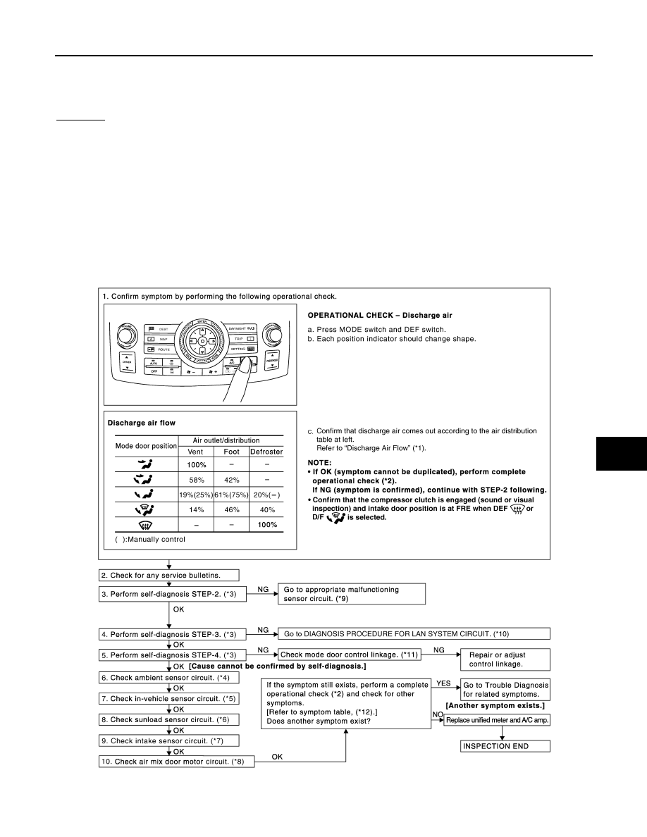
SYMPTOM
• Air outlet does not change.
• Mode door motor does not operate normally.
INSPECTION FLOW
SJIA1806E
ATC-58
< SERVICE INFORMATION >
TROUBLE DIAGNOSIS
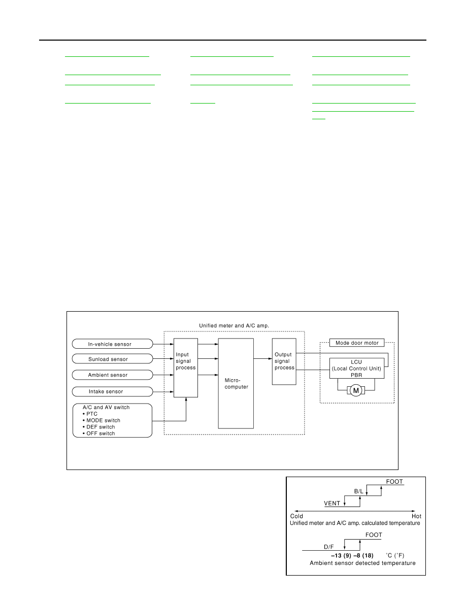
SYSTEM DESCRIPTION
Component Parts
Mode door control system components are:
• Unified meter and A/C amp.
• Mode door motor (LCU)
• A/C LAN system (PBR built-in mode door motor, air mix door motor and intake door motor)
• In-vehicle sensor
• Ambient sensor
• Sunload sensor
• Intake sensor
System Operation
The unified meter and A/C amp. receives data from each of the sensors. The unified meter and A/C amp.
sends air mix door, mode door and intake door opening angle data to the air mix door motor LCUs, mode door
motor LCU and intake door motor LCU.
The air mix door motors, mode door motor and intake door motor read their respective signals according to the
address signal. Opening angle indication signals received from the unified meter and A/C amp. and each of
the motor position sensors are compared by the LCUs in each door motor with the existing decision and open-
ing angles. Subsequently, HOT/COLD, DEF/VENT and FRE/REC operation is selected. The new selection
data are returned to the unified meter and A/C amp.
Mode Door Control Specification
*1
*2
*3
ATC-43, "Self-Diagnosis Function"
,
see No. 4 to 6.
*4
ATC-86, "Ambient Sensor Circuit"
*5
ATC-88, "In-vehicle Sensor Circuit"
*6
ATC-91, "Sunload Sensor Circuit"
*7
ATC-94, "Intake Sensor Circuit"
*8
ATC-59, "Air Mix Door Motor Circuit"
*9
ATC-43, "Self-Diagnosis Function"
,
see No. 13.
*10
*11
*12
ATC-32, "How to Perform Trouble Di-
agnosis for Quick and Accurate Re-
pair"
SJIA1585E
RJIA1778E

TROUBLE DIAGNOSIS
ATC-59
< SERVICE INFORMATION >
C
D
E
F
G
H
I
K
L
M
A
B
ATC
N
O
P
COMPONENT DESCRIPTION
Mode Door Motor
The mode door motor is attached to the heater & cooling unit assem-
bly. It rotates so that air is discharged from the outlet set by the uni-
fied meter and A/C amp. Motor rotation is conveyed to a link which
activates the mode door.
DIAGNOSIS PROCEDURE FOR MODE DOOR MOTOR
SYMPTOM: Mode door motor does not operate normally.
Perform diagnosis procedure. Refer to
Air Mix Door Motor Circuit
INFOID:0000000001328186
SYMPTOM
• Discharge air temperature does not change.
• Air mix door motor does not operate normally.
INSPECTION FLOW
RJIA0890E
Нет комментариевНе стесняйтесь поделиться с нами вашим ценным мнением.
Текст