Infiniti FX35 / FX45. Manual — part 120
ATC-76
< SERVICE INFORMATION >
TROUBLE DIAGNOSIS
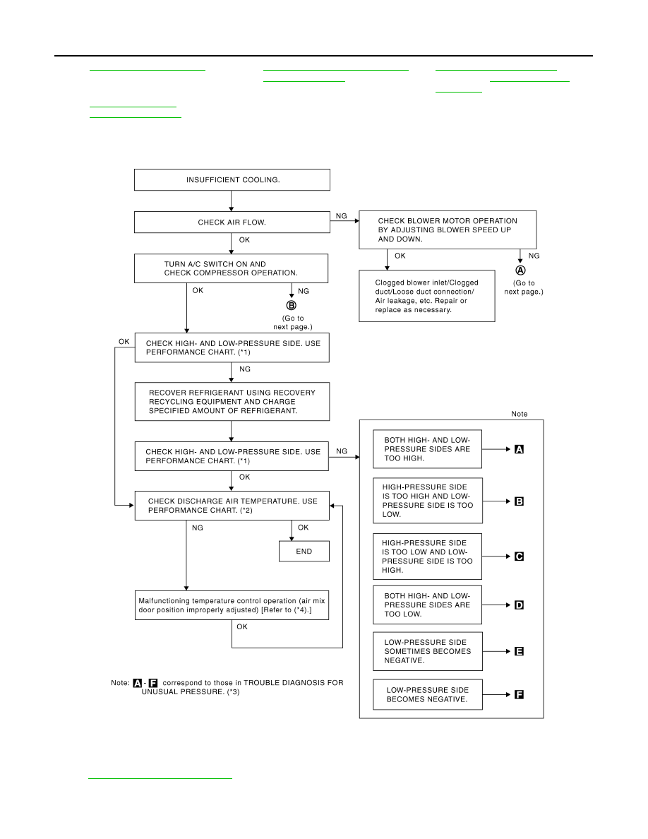
PERFORMANCE TEST DIAGNOSIS
*10
*11
ATC-4, "Precaution for Working with
HFC-134a (R-134a)"
*12
(VK45DE)
*13
(VQ35DE) or
*1
"PERFORMANCE CHART"
*2
"PERFORMANCE CHART"
*3
"TROUBLE DIAGNOSIS FOR UN-
USUAL PRESSURE"
*4
ATC-59, "Air Mix Door Motor Circuit"
SJIA1226E
TROUBLE DIAGNOSIS
ATC-77
< SERVICE INFORMATION >
C
D
E
F
G
H
I
K
L
M
A
B
ATC
N
O
P
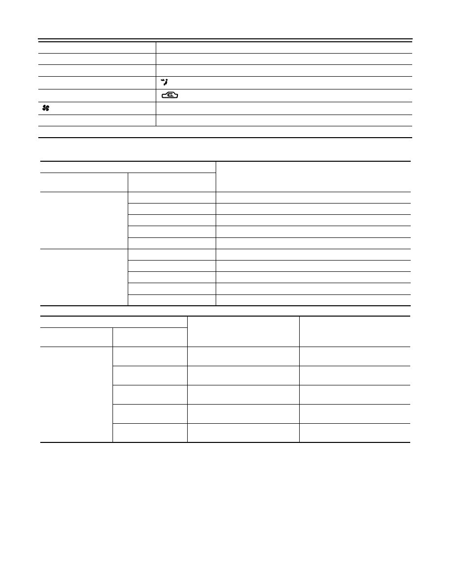
PERFORMANCE CHART
Test Condition
Testing must be performed as follows:
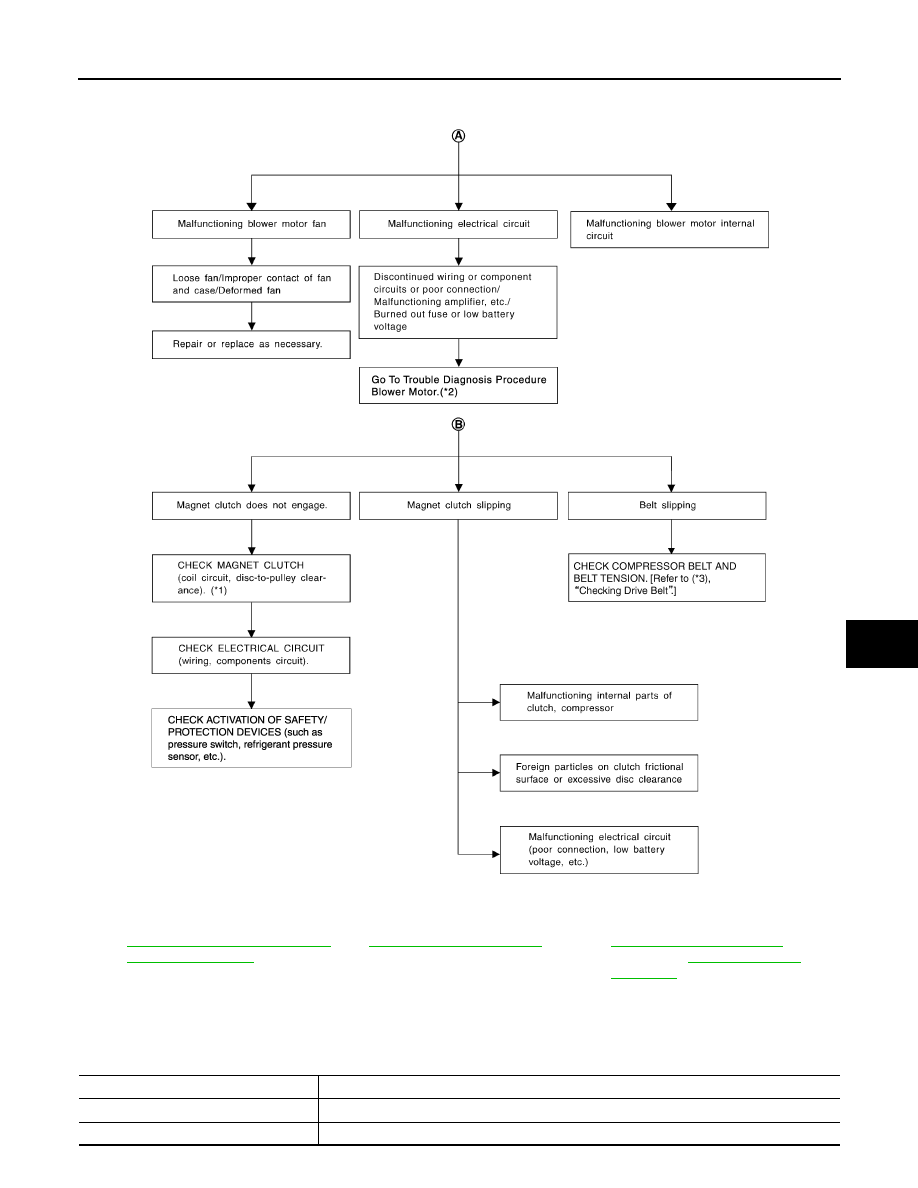
*1
ATC-125, "Removal and Installation
of Compressor Clutch"
*2
ATC-64, "Blower Motor Circuit"
*3
(VQ35DE) or
(VK45DE)
SJIA1642E
Vehicle condition
Indoors or in the shade (in a well-ventilated place)
Doors
Closed
Door windows
Open
ATC-78
< SERVICE INFORMATION >
TROUBLE DIAGNOSIS
Test Reading
Recirculating-to-discharge Air Temperature Table
Ambient Air Temperature-to-operating Pressure Table
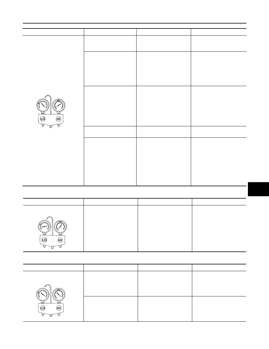
TROUBLE DIAGNOSIS FOR UNUSUAL PRESSURE
Whenever system’s high and/or low side pressure(s) is/are unusual, diagnose using a manifold gauge. The
marker above the gauge scale in the following tables indicates the standard (usual) pressure range. Since the
standard (usual) pressure, however, differs from vehicle to vehicle, refer to above table (Ambient air tempera-
ture-to-operating pressure table).
Both High- and Low-pressure Sides are Too High
Hood
Open
TEMP.
Max. COLD
Mode switch
(Ventilation) set
Intake switch
(Recirculation) set
Fan (blower) speed
Max. speed set
Engine speed
Idle speed
Operate the air conditioning system for 10 minutes before taking measurements.
Inside air (Recirculating air) at blower assembly inlet
Discharge air temperature at center ventilator
°
C (
°
F)
Relative humidity
%
Air temperature
°
C (
°
F)
50 - 60
20 (68)
11.2 - 13.2 (52 - 56)
25 (77)
12.2 - 14.8 (54 - 59)
30 (86)
15.5 - 18.6 (60 - 65)
35 (95)
21.0 - 24.5 (70 - 76)
40 (104)
28.7 - 32.6 (84 - 91)
60 - 70
20 (68)
13.2 - 15.2 (56 - 59)
25 (77)
14.8 - 17.3 (59 - 63)
30 (86)
18.6 - 21.6 (65 - 71)
35 (95)
24.5 - 28.0 (76 - 82)
40 (104)
32.6 - 36.5 (91 - 98)
Ambient air
High-pressure (Discharge side)
kPa (kg/cm
2
, psi)
Low-pressure (Suction side)
kPa (kg/cm
2
, psi)
Relative humidity
%
Air temperature
°
C (
°
F)
50 - 70
20 (68)
961 - 1,167
(9.8 - 11.9, 139 - 169)
216 - 265
(2.2 - 2.7, 31 - 38)
25 (77)
1,108 - 1,353
(11.3 - 13.8, 161 - 196)
230 - 281
(2.3 - 2.9, 33 - 41)
30 (86)
1,275 - 1,549
(13.0 - 15.8, 185 - 225)
261 - 320
(2.7 - 3.3, 38 - 46)
35 (95)
1,549 - 1,893
(15.8 - 19.3, 225 - 274)
297 - 364
(3.0 - 3.7, 43 - 53)
40 (104)
1,814 - 2,216
(18.5 - 22.6, 263 - 321)
357 - 435
(3.6 - 4.4, 52 - 63)
Vehicle condition
Indoors or in the shade (in a well-ventilated place)
TROUBLE DIAGNOSIS
ATC-79
< SERVICE INFORMATION >
C
D
E
F
G
H
I
K
L
M
A
B
ATC
N
O
P
High-pressure Side is Too High and Low-pressure Side is Too Low
High-pressure Side is Too Low and Low-pressure Side is Too High
Both High- and Low-pressure Sides are Too Low
Gauge indication
Refrigerant cycle
Probable cause
Corrective action
Both high- and low-pressure sides
are too high.
The pressure returns to nor-
mal soon after water is
splashed on condenser.
Excessive refrigerant charge in
refrigeration cycle.
Reduce refrigerant until speci-
fied pressure is obtained.
Air suction by cooling fan is in-
sufficient.
Insufficient condenser cooling
performance.
↓
1.
Condenser fins are
clogged.
2.
Improper fan rotation of
cooling fan.
• Clean condenser.
• Check and repair cooling fan
as necessary.
• Low-pressure pipe is not
cold.
• When compressor is
stopped high-pressure val-
ue quickly drops by approx-
imately 196 kPa (2 kg/cm
2
,
28 psi). It then decreases
gradually thereafter.
Poor heat exchange in con-
denser
(After compressor operation
stops, high-pressure decreas-
es too slowly.).
↓
Air in refrigeration cycle.
Evacuate repeatedly and re-
charge system.
Engine tends to overheat.
Engine cooling systems mal-
function.
Check and repair each engine
cooling system.
• An area of the low-pressure
pipe is colder than areas
near the evaporator outlet.
• Low-pressure pipe is some-
times covered with frost.
• Excessive liquid refrigerant
on low-pressure side.
• Excessive refrigerant dis-
charge flow.
• Expansion valve is open a lit-
tle compared with the speci-
fication.
↓
Improper expansion valve ad-
justment.
Replace expansion valve.
AC359A
Gauge indication
Refrigerant cycle
Probable cause
Corrective action
High-pressure side is too high and
low-pressure side is too low.
Upper side of condenser and
high-pressure side are hot,
however, liquid tank is not so
hot.
High-pressure tube or parts lo-
cated between compressor
and condenser are clogged or
crushed.
• Check and repair or replace
malfunctioning parts.
• Check lubricant for contami-
nation.
AC360A
Gauge indication
Refrigerant cycle
Probable cause
Corrective action
High-pressure side is too low and
low-pressure side is too high.
High- and low-pressure sides
become equal soon after com-
pressor operation stops.
Compressor pressure opera-
tion is improper.
↓
Damaged inside compressor
packings.
Replace compressor.
No temperature difference be-
tween high- and low-pressure
sides.
Compressor pressure opera-
tion is improper.
↓
Damaged inside compressor
packings.
Replace compressor.
AC356A
Нет комментариевНе стесняйтесь поделиться с нами вашим ценным мнением.
Текст