Infiniti FX35 / FX45. Manual — part 355
DTC P0101 MAF SENSOR
EC-181
< SERVICE INFORMATION >
[VQ35DE]
C
D
E
F
G
H
I
J
K
L
M
A
EC
N
P
O
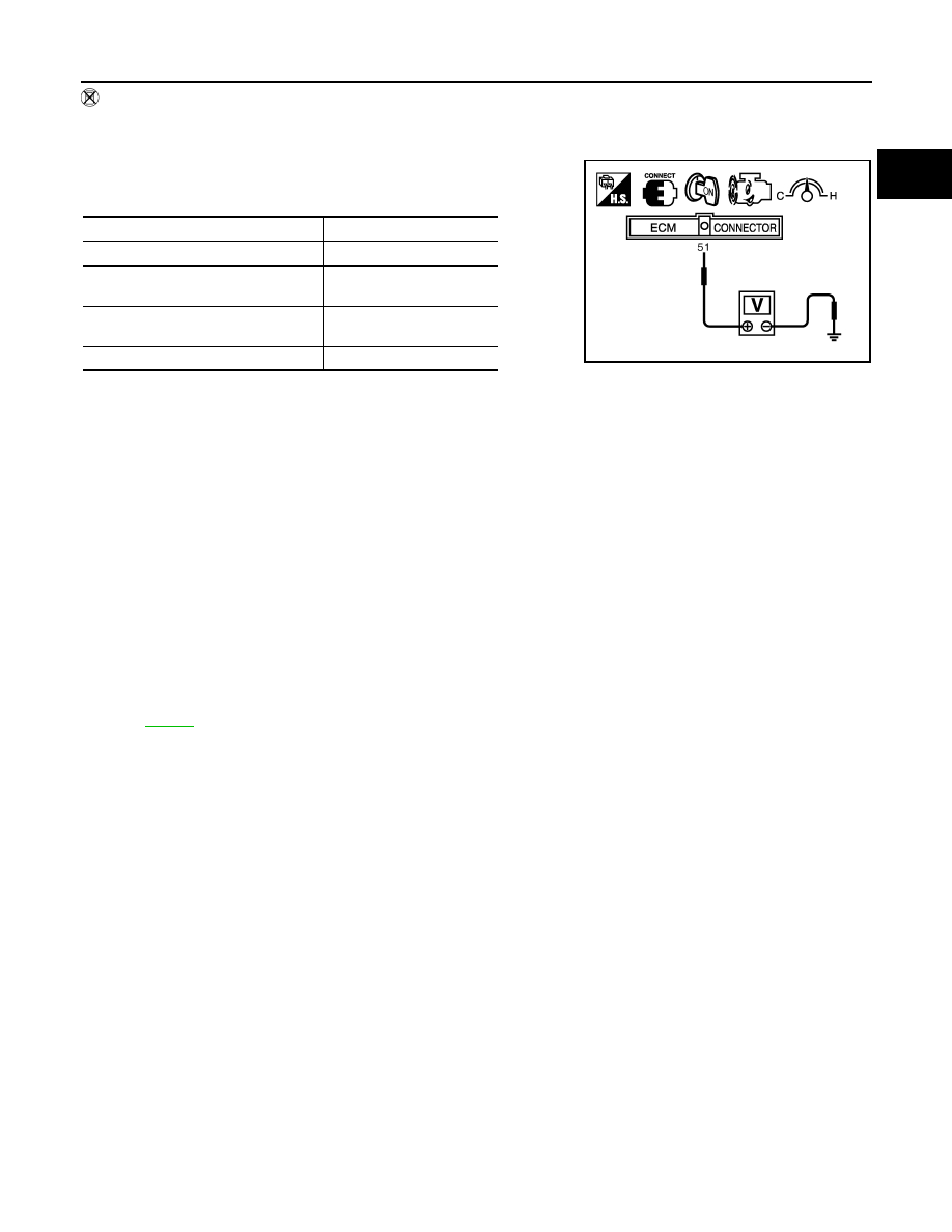
Without CONSULT-III
1.
Reconnect all harness connectors disconnected.
2.
Start engine and warm it up to normal operating temperature.
3.
Check voltage between ECM terminal 51 (Mass air flow sensor
signal) and ground.
*: Check for linear voltage rise in response to engine being increased to about 4,000 rpm.
4.
If the voltage is out of specification, proceed the following.
a.
Check for the cause of uneven air flow through mass air flow sensor. Refer to following.
• Crushed air ducts
• Malfunctioning seal of air cleaner element
• Uneven dirt of air cleaner element
• Improper specification of intake air system parts
b.
If NG, repair or replace malfunctioning part and perform step 2 and 3 again.
If OK, go to next step.
5.
Turn ignition switch OFF.
6.
Disconnect mass air flow sensor harness connector and reconnect it again.
7.
Perform step 2 and 3 again.
8.
If NG, clean or replace mass air flow sensor.
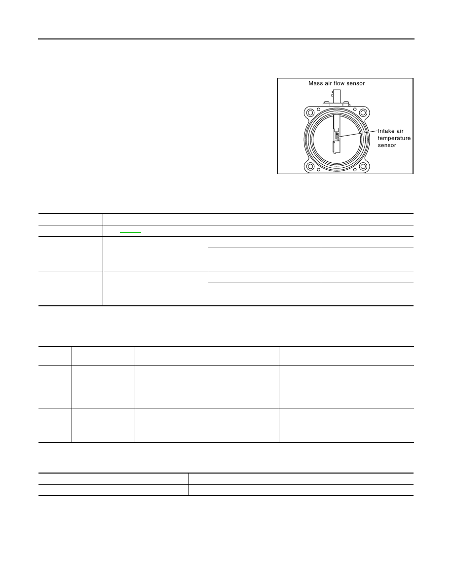
Removal and Installation
INFOID:0000000001325997
MASS AIR FLOW SENSOR
Condition
Voltage V
Ignition switch ON (Engine stopped.)
Approx. 0.4
Idle (Engine is warmed-up to normal
operating temperature.)
1.0 - 1.2
2,500 rpm (Engine is warmed-up to
normal operating temperature.)
1.6 - 2.0
Idle to about 4,000 rpm
1.0 - 1.2 to Approx. 2.4*
PBIB1106E
EC-182
< SERVICE INFORMATION >
[VQ35DE]
DTC P0102, P0103 MAF SENSOR
DTC P0102, P0103 MAF SENSOR
Component Description
INFOID:0000000001325998
The mass air flow (MAF) sensor is placed in the stream of intake air.
It measures the intake flow rate by measuring a part of the entire
intake flow. The mass air flow sensor controls the temperature of the
hot wire to a certain amount. The heat generated by the hot wire is
reduced as the intake air flows around it. The more air, the greater
the heat loss.
Therefore, electric current is supplied to hot wire is changed to main-
tain the temperature of the hot wire as air flow increases. The ECM
detects the air flow by means of this current change.
CONSULT-III Reference Value in Data Monitor Mode
INFOID:0000000001325999
Specification data are reference values.
On Board Diagnosis Logic
INFOID:0000000001326000
These self-diagnoses have the one trip detection logic.
FAIL-SAFE MODE
When the malfunction is detected, the ECM enters fail-safe mode and the MIL lights up.
DTC Confirmation Procedure
INFOID:0000000001326001
NOTE:
If DTC Confirmation Procedure has been previously conducted, always turn ignition switch OFF and wait at
least 10 seconds before conducting the next test.
PROCEDURE FOR DTC P0102
PBIB1604E
MONITOR ITEM
CONDITION
SPECIFICATION
MAS A/F SE-B1
See
CAL/LD VALUE
• Engine: After warming up
• Selector lever: P or N
• Air conditioner switch: OFF
• No load
Idle
5% - 35%
2,500 rpm
5% - 35%
MASS AIRFLOW
• Engine: After warming up
• Selector lever: P or N
• Air conditioner switch: OFF
• No load
Idle
2.0 - 6.0 g·m/s
2,500 rpm
7.0 - 20.0 g·m/s
DTC No.
Trouble diagnosis
name
DTC detecting condition
Possible cause
P0102
0102
Mass air flow sensor
circuit low input
An excessively low voltage from the sensor is sent
to ECM.
• Harness or connectors
(Mass air flow sensor circuit is open or short-
ed.)
• Intake air leaks
• Mass air flow sensor
P0103
0103
Mass air flow sensor
circuit high input
An excessively high voltage from the sensor is
sent to ECM.
• Harness or connectors
(Mass air flow sensor circuit is open or short-
ed.)
• Mass air flow sensor
Detected items
Engine operating condition in fail-safe mode
Mass air flow sensor circuit
Engine speed will not rise more than 2,400 rpm due to the fuel cut.
DTC P0102, P0103 MAF SENSOR
EC-183
< SERVICE INFORMATION >
[VQ35DE]
C
D
E
F
G
H
I
J
K
L
M
A
EC
N
P
O
1.
Start engine and wait at least 5 seconds.
2.
Check DTC.
3.
If DTC is detected, go to
.
PROCEDURE FOR DTC P0103
1.
Turn ignition switch ON and wait at least 5 second.
2.
Check DTC.
3.
If DTC is detected, go to
.
If DTC is not detected, go to next step.
4.
Start engine and wait at least 5 seconds.
5.
Check DTC.
6.
If DTC is detected, go to
.

EC-184
< SERVICE INFORMATION >
[VQ35DE]
DTC P0102, P0103 MAF SENSOR
Wiring Diagram
INFOID:0000000001326002
Specification data are reference values and are measured between each terminal and ground.
CAUTION:
Do not use ECM ground terminals when measuring input/output voltage. Doing so may result in dam-
age to the ECM's transistor. Use a ground other than ECM terminals, such as the ground.
TBWM1381E
Нет комментариевНе стесняйтесь поделиться с нами вашим ценным мнением.
Текст