Infiniti FX35 / FX45. Manual — part 356
DTC P0102, P0103 MAF SENSOR
EC-185
< SERVICE INFORMATION >
[VQ35DE]
C
D
E
F
G
H
I
J
K
L
M
A
EC
N
P
O
Diagnosis Procedure
INFOID:0000000001326003
1.
INSPECTION START
Which malfunction (P0102 or P0103) is duplicated?
P0102 or P0103
P0102 >> GO TO 2.
P0103 >> GO TO 3.
2.
CHECK INTAKE SYSTEM
Check the following for connection.
• Air duct
• Vacuum hoses
• Intake air passage between air duct and intake manifold
OK or NG
OK
>> GO TO 3.
NG
>> Reconnect the parts.
3.
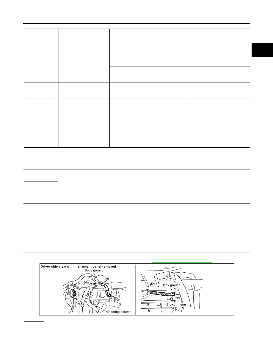
CHECK GROUND CONNECTIONS
1.
Turn ignition switch OFF.
2.
Loosen and retighten ground screw on the body. Refer to
OK or NG
OK
>> GO TO 4.
NG
>> Repair or replace ground connections.
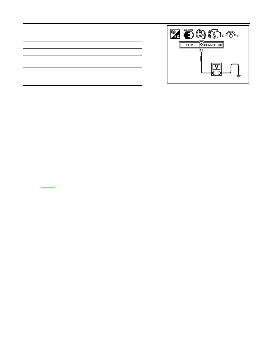
TER-
MI-
NAL
NO.
WIRE
COLOR
ITEM
CONDITION
DATA (DC Voltage)
51
L/W
Mass air flow sensor
[Engine is running]
• Warm-up condition
• Idle speed
1.0 - 1.2V
[Engine is running]
• Warm-up condition
• Engine speed: 2,500 rpm
1.6 - 2.0V
67
B/W
Sensor ground
[Engine is running]
• Warm-up condition
• Idle speed
Approximately 0V
111
W/B
ECM relay
(Self shut-off)
[Engine is running]
[Ignition switch: OFF]
• For a few seconds after turning ignition
switch OFF
0 - 1.5V
[Ignition switch: OFF]
• More than a few seconds after turning igni-
tion switch OFF
BATTERY VOLTAGE
(11 - 14V)
119
120
R
R/B
Power supply for ECM
[Ignition switch: ON]
BATTERY VOLTAGE
(11 - 14V)
PBIB2625E
EC-186
< SERVICE INFORMATION >
[VQ35DE]
DTC P0102, P0103 MAF SENSOR
4.
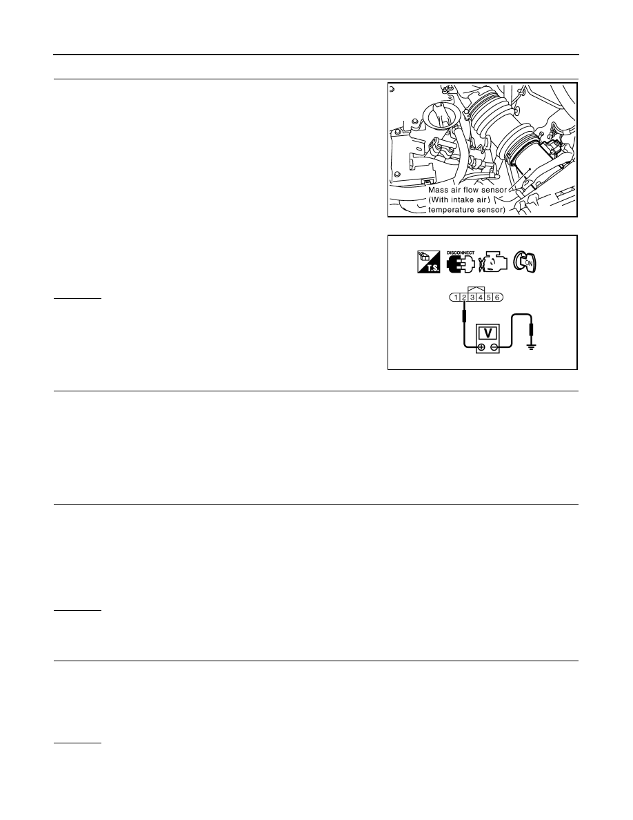
CHECK MAF SENSOR POWER SUPPLY CIRCUIT
1.
Disconnect mass air flow (MAF) sensor harness connector.
2.
Turn ignition switch ON.
3.
Check voltage between MAF sensor terminal 2 and ground with
CONSULT-III or tester.
OK or NG
OK
>> GO TO 6.
NG
>> GO TO 5.
5.
DETECT MALFUNCTIONING PART
Check the following.
• Harness connectors E211, M41
• Harness connectors M82, F102
• Harness for open or short between IPDM E/R and mass air flow sensor
• Harness for open or short between mass air flow sensor and ECM
>> Repair open circuit or short to ground or short to power in harness or connectors.
6.
CHECK MAF SENSOR GROUND CIRCUIT FOR OPEN AND SHORT
1.
Turn ignition switch OFF.
2.
Disconnect ECM harness connector.
3.
Check harness continuity between MAF sensor terminal 3 and ECM terminal 67.
Refer to Wiring Diagram.
4.
Also check harness for short to ground and short to power.
OK or NG
OK
>> GO TO 7.
NG
>> Repair open circuit or short to ground or short to power in harness or connectors.
7.
CHECK MAF SENSOR INPUT SIGNAL CIRCUIT FOR OPEN AND SHORT
1.
Check harness continuity between MAF sensor terminal 4 and ECM terminal 51.
Refer to Wiring Diagram.
2.
Also check harness for short to ground and short to power.
OK or NG
OK
>> GO TO 8.
NG
>> Repair open circuit or short to ground or short to power in harness or connectors.
PBIB1565E
Voltage: Battery voltage
PBIB1168E
Continuity should exist.
Continuity should exist.

DTC P0102, P0103 MAF SENSOR
EC-187
< SERVICE INFORMATION >
[VQ35DE]
C
D
E
F
G
H
I
J
K
L
M
A
EC
N
P
O
8.
CHECK MASS AIR FLOW SENSOR
EC-187, "Component Inspection"
OK or NG
OK
>> GO TO 9.
NG
>> Replace mass air flow sensor.
9.
CHECK INTERMITTENT INCIDENT
>> INSPECTION END
Component Inspection
INFOID:0000000001583029
MASS AIR FLOW SENSOR
With CONSULT-III
1.
Reconnect all harness connectors disconnected.
2.
Start engine and warm it up to normal operating temperature.
3.
Connect CONSULT-III and select “DATA MONITOR” mode.
4.
Select “MAS A/F SE-B1” and check indication under the following conditions.
*: Check for linear voltage rise in response to engine being increased to about 4,000 rpm.
5.
If the voltage is out of specification, proceed the following.
a.
Check for the cause of uneven air flow through mass air flow sensor. Refer to following.
• Crushed air ducts
• Malfunctioning seal of air cleaner element
• Uneven dirt of air cleaner element
• Improper specification of intake air system parts
b.
If NG, repair or replace malfunctioning part and perform step 2 to 4 again.
If OK, go to next step.
6.
Turn ignition switch OFF.
7.
Disconnect mass air flow sensor harness connector and reconnect it again.
8.
Perform step 2 to 4 again.
9.
If NG, clean or replace mass air flow sensor.
Without CONSULT-III
1.
Reconnect all harness connectors disconnected.
2.
Start engine and warm it up to normal operating temperature.
Condition
MAS A/F SE-B1 (V)
Ignition switch ON (Engine stopped.)
Approx. 0.4
Idle (Engine is warmed-up to normal
operating temperature.)
1.0 - 1.2
2,500 rpm (Engine is warmed-up to
normal operating temperature.)
1.6 - 2.0
Idle to about 4,000 rpm
1.0 - 1.2 to Approx. 2.4*
EC-188
< SERVICE INFORMATION >
[VQ35DE]
DTC P0102, P0103 MAF SENSOR
3.
Check voltage between ECM terminal 51 (Mass air flow sensor
signal) and ground.
*: Check for linear voltage rise in response to engine being increased to about 4,000 rpm.
4.
If the voltage is out of specification, proceed the following.
a.
Check for the cause of uneven air flow through mass air flow sensor. Refer to following.
• Crushed air ducts
• Malfunctioning seal of air cleaner element
• Uneven dirt of air cleaner element
• Improper specification of intake air system parts
b.
If NG, repair or replace malfunctioning part and perform step 2 and 3 again.
If OK, go to next step.
5.
Turn ignition switch OFF.
6.
Disconnect mass air flow sensor harness connector and reconnect it again.
7.
Perform step 2 and 3 again.
8.
If NG, clean or replace mass air flow sensor.
Removal and Installation
INFOID:0000000001326005
MASS AIR FLOW SENSOR
Condition
Voltage V
Ignition switch ON (Engine stopped.)
Approx. 0.4
Idle (Engine is warmed-up to normal
operating temperature.)
1.0 - 1.2
2,500 rpm (Engine is warmed-up to
normal operating temperature.)
1.6 - 2.0
Idle to about 4,000 rpm
1.0 - 1.2 to Approx. 2.4*
PBIB1106E
Нет комментариевНе стесняйтесь поделиться с нами вашим ценным мнением.
Текст