Infiniti FX35 / FX45. Manual — part 447
ASCD INDICATOR
EC-549
< SERVICE INFORMATION >
[VQ35DE]
C
D
E
F
G
H
I
J
K
L
M
A
EC
N
P
O
OK or NG
OK
>> INSPECTION END
NG
>> GO TO 2.
2.
CHECK DTC
Check that DTC U1000 or U1001 is not displayed.
OK or NG
OK
>> GO TO 3.
NG
>> Perform trouble diagnoses for DTC U1000, U1001. Refer to
.
3.
CHECK DTC WITH “UNIFIED METER AND A/C AMP.”
DI-27, "CONSULT-III Function (METER/M&A)"
OK or NG
OK
>> GO TO 4.
NG
>> Go to
DI-30, "DTC [B2202] Meter Communication Circuit"
4.
CHECK INTERMITTENT INCIDENT
>> INSPECTION END
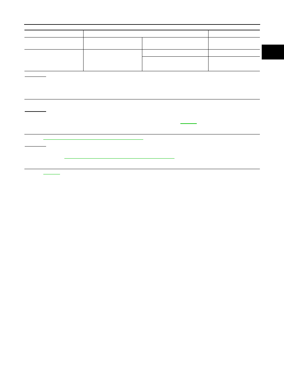
ASCD INDICATOR
CONDITION
SPECIFICATION
CRUISE LAMP
• Ignition switch: ON
• MAIN switch: pressed at the 1st
time
→
at the 2nd time
ON
→
OFF
SET LAMP
• MAIN switch: ON
• When vehicle speed is be-
tween 40km/h (25MPH) and
144km/h (89MPH)
ASCD: Operating
ON
ASCD: Not operating
OFF
EC-550
< SERVICE INFORMATION >
[VQ35DE]
ELECTRICAL LOAD SIGNAL
ELECTRICAL LOAD SIGNAL
Description
INFOID:0000000001326435
The electrical load signal (Headlamp switch signal, etc.) is transferred through the CAN communication line
from BCM to ECM via IPDM E/R.
CONSULT-III Reference Value in Data Monitor Mode
INFOID:0000000001326436
Specification data are reference values.
Diagnosis Procedure
INFOID:0000000001326437
1.
CHECK LOAD SIGNAL CIRCUIT OVERALL FUNCTION-I
1.
Turn ignition switch ON.
2.
Connect CONSULT-III and select “DATA MONITOR” mode.
3.
Select “LOAD SIGNAL” and check indication under the following conditions.
OK or NG
OK
>> GO TO 2.
NG
>> GO TO 4.
2.
CHECK LOAD SIGNAL CIRCUIT OVERALL FUNCTION-II
Check “LOAD SIGNAL” indication under the following conditions.
OK or NG
OK
>> GO TO 3.
NG
>> GO TO 5.
3.
CHECK HEATER FAN SIGNAL CIRCUIT OVERALL FUNCTION
Check “HEATER FAN SW” in “DATA MONITOR” mode with CONSULT-III under the following conditions.
OK or NG
OK
>> INSPECTION END
NG
>> GO TO 6.
4.
CHECK REAR WINDOW DEFOGGER SYSTEM
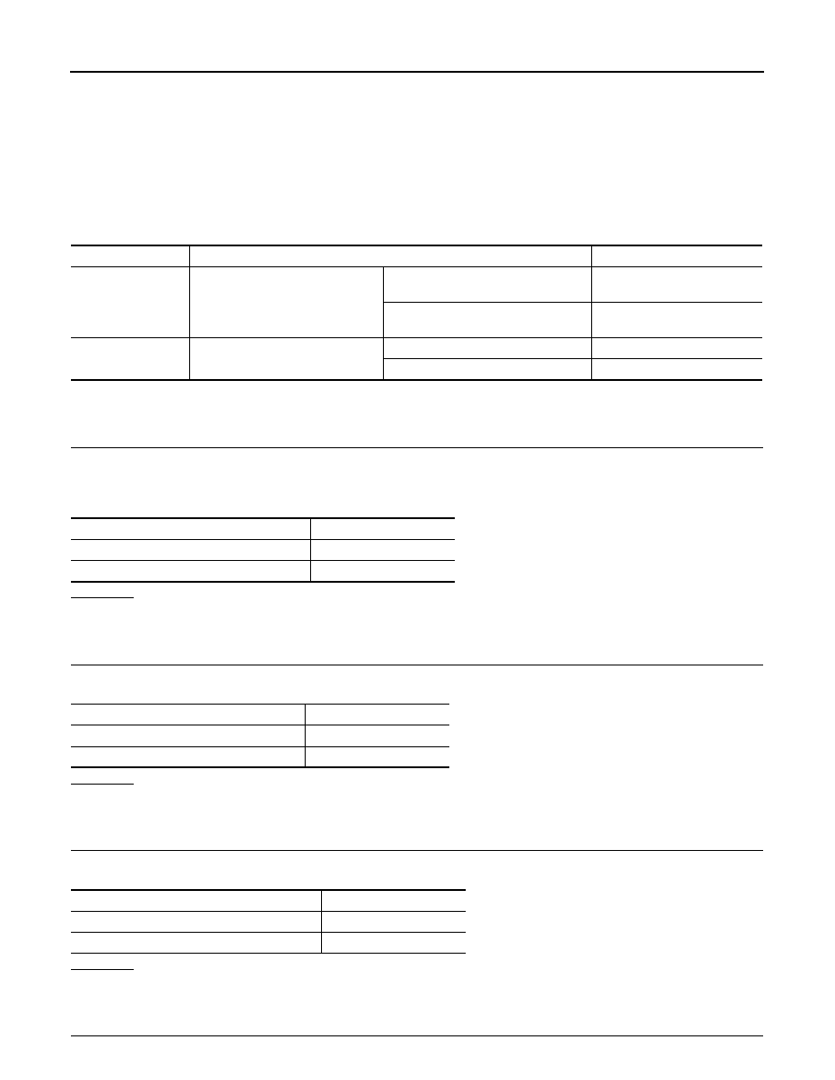
MONITOR ITEM
CONDITION
SPECIFICATION
LOAD SIGNAL
• Ignition switch: ON
Rear window defogger switch is ON
and/or lighting switch is in 2nd.
ON
Rear window defogger switch is OFF
and lighting switch is OFF.
OFF
HEATER FAN SW
• Engine: After warming up, idle the
engine
Heater fan: Operating.
ON
Heater fan: Not operating
OFF
Condition
Indication
Rear window defogger switch: ON
ON
Rear window defogger switch: OFF
OFF
Condition
Indication
Lighting switch: ON at 2nd position
ON
Lighting switch: OFF
OFF
Condition
Indication
Heater fan: Operating
ON
Heater fan: Not operating
OFF
ELECTRICAL LOAD SIGNAL
EC-551
< SERVICE INFORMATION >
[VQ35DE]
C
D
E
F
G
H
I
J
K
L
M
A
EC
N
P
O
>> INSPECTION END
5.
CHECK HEADLAMP SYSTEM
>> INSPECTION END
6.
CHECK HEATER FAN CONTROL SYSTEM
.
>> INSPECTION END
EC-552
< SERVICE INFORMATION >
[VQ35DE]
FUEL INJECTOR
FUEL INJECTOR
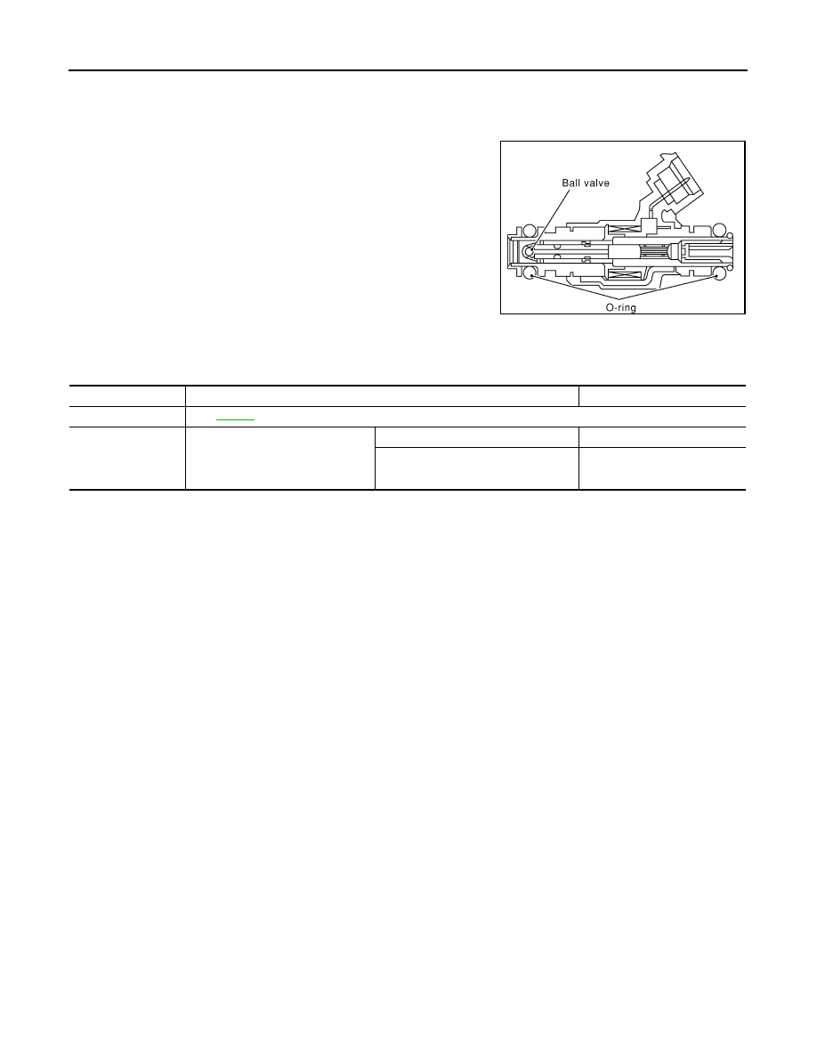
Component Description
INFOID:0000000001326438
The fuel injector is a small, precise solenoid valve. When the ECM
supplies a ground to the fuel injector circuit, the coil in the fuel injec-
tor is energized. The energized coil pulls the Ball valve back and
allows fuel to flow through the fuel injector into the intake manifold.
The amount of fuel injected depends upon the fuel injection pulse
duration. Pulse duration is the length of time the fuel injector remains
open. The ECM controls the injection pulse duration based on
engine fuel needs.
CONSULT-III Reference Value in Data Monitor Mode
INFOID:0000000001326439
Specification data are reference values.
SEF375Z
MONITOR ITEM
CONDITION
SPECIFICATION
B/FUEL SCHDL
See
INJ PULSE-B1
INJ PULSE-B2
• Engine: After warming up
• Selector lever: P or N
• Air conditioner switch: OFF
• No load
Idle
2.0 - 3.0 msec
2,000 rpm
1.9 - 2.9 msec
Нет комментариевНе стесняйтесь поделиться с нами вашим ценным мнением.
Текст