Infiniti FX35 / FX45. Manual — part 446
ASCD BRAKE SWITCH
EC-545
< SERVICE INFORMATION >
[VQ35DE]
C
D
E
F
G
H
I
J
K
L
M
A
EC
N
P
O
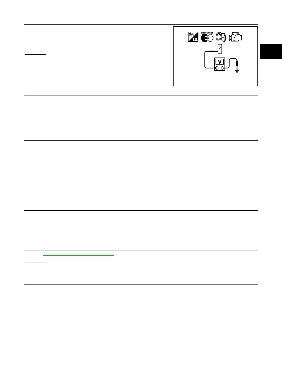
4.
Check voltage between ASCD brake switch terminal 1 and
ground with CONSULT-III or tester.
OK or NG
OK
>> GO TO 4.
NG
>> GO TO 3.
3.
DETECT MALFUNCTIONING PART
Check the following.
• Fuse block (J/B) connector E201
• 10A fuse
• Harness for open or short between ASCD brake switch and fuse
>> Repair open circuit or short to ground or short power in harness or connectors.
4.
CHECK ASCD BRAKE SWITCH INPUT SIGNAL CIRCUIT FOR OPEN AND SHORT
1.
Turn ignition switch OFF.
2.
Disconnect ECM harness connector.
3.
Check harness continuity between ECM terminal 108 and ASCD brake switch terminal 2.
Refer to Wiring Diagram.
4.
Also check harness for short to ground and short to power.
OK or NG
OK
>> GO TO 6.
NG
>> GO TO 5.
5.
DETECT MALFUNCTIONING PART
Check the following.
• Harness connectors E211, M41
• Harness for open or short between ECM and ASCD brake switch
>> Repair open circuit or short to ground or short power in harness or connectors.
6.
CHECK ASCD BRAKE SWITCH
EC-545, "Component Inspection"
OK or NG
OK
>> GO TO 7.
NG
>> Replace ASCD brake switch.
7.
CHECK INTERMITTENT INCIDENT
>> INSPECTION END
Component Inspection
INFOID:0000000001326430
ASCD BRAKE SWITCH
1.
Turn ignition switch OFF.
2.
Disconnect ASCD brake switch harness connector.
Voltage: Battery voltage
PBIB0857E
Continuity should exist.
EC-546
< SERVICE INFORMATION >
[VQ35DE]
ASCD BRAKE SWITCH
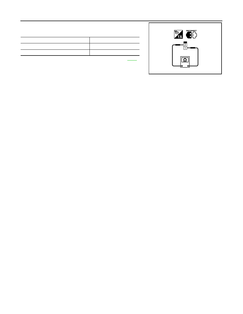
3.
Check continuity between ASCD brake switch terminals 1 and 2
under the following conditions.
If NG, adjust ASCD brake switch installation, refer to
perform step 3 again.
Condition
Continuity
Brake pedal: Fully released
Should exist.
Brake pedal: Slightly depressed
Should not exist.
SEC023D

ASCD INDICATOR
EC-547
< SERVICE INFORMATION >
[VQ35DE]
C
D
E
F
G
H
I
J
K
L
M
A
EC
N
P
O
ASCD INDICATOR
Component Description
INFOID:0000000001326431
ASCD indicator lamp illuminates to indicate ASCD operation status. Lamp has two indicators, CRUISE, SET,
and is integrated in combination meter.
CRUISE indicator illuminates when MAIN switch on ASCD steering switch is turned ON to indicated that
ASCD system is ready for operation.
SET indicator illuminates when following conditions are met.
• CRUISE indicator is illuminated.
• SET/COAST switch on ASCD steering switch is turned ON while vehicle speed is within the range of ASCD
setting.
SET indicator remains lit during ASCD control.
Refer to
CONSULT-III Reference Value in Data Monitor Mode
INFOID:0000000001326432
Specification data are reference value.
MONITOR ITEM
CONDITION
SPECIFICATION
CRUISE LAMP
• Ignition switch: ON
• ON/OFF (MAIN) switch: Pressed
at the 1st time
→
at the 2nd time
ON
→
OFF
SET LAMP
• MAIN switch: ON
• When vehicle speed is be-
tween 40km/h (25MPH) and
144km/h (89MPH)
ASCD: Operating
ON
ASCD: Not operating
OFF
EC-548
< SERVICE INFORMATION >
[VQ35DE]
ASCD INDICATOR
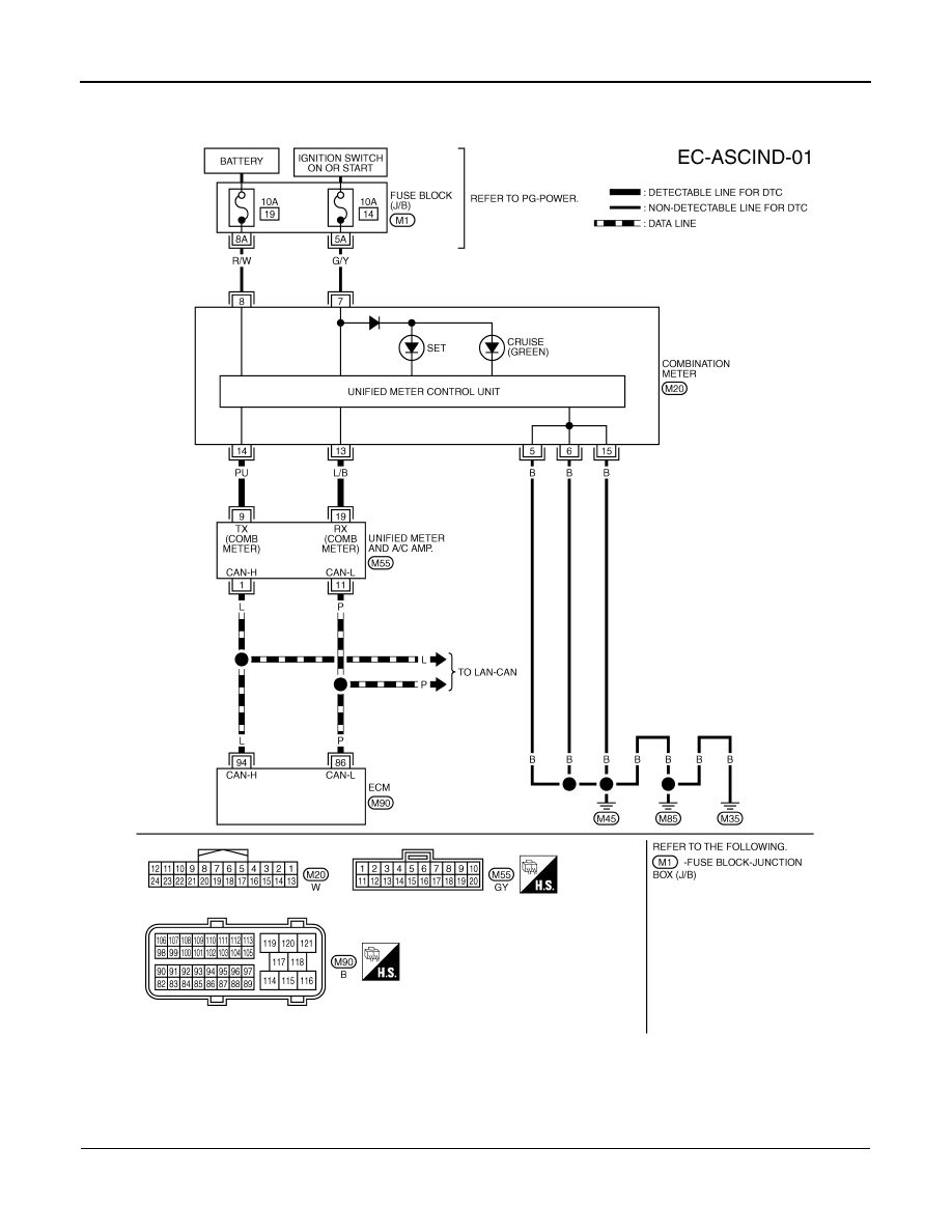
Wiring Diagram
INFOID:0000000001326433
Diagnosis Procedure
INFOID:0000000001326434
1.
CHECK OVERALL FUNCTION
Check ASCD indicator under the following conditions.
TBWM1412E
Нет комментариевНе стесняйтесь поделиться с нами вашим ценным мнением.
Текст