Infiniti FX35 / FX45. Manual — part 445
DTC P2A00, P2A03 A/F SENSOR 1
EC-541
< SERVICE INFORMATION >
[VQ35DE]
C
D
E
F
G
H
I
J
K
L
M
A
EC
N
P
O
3.
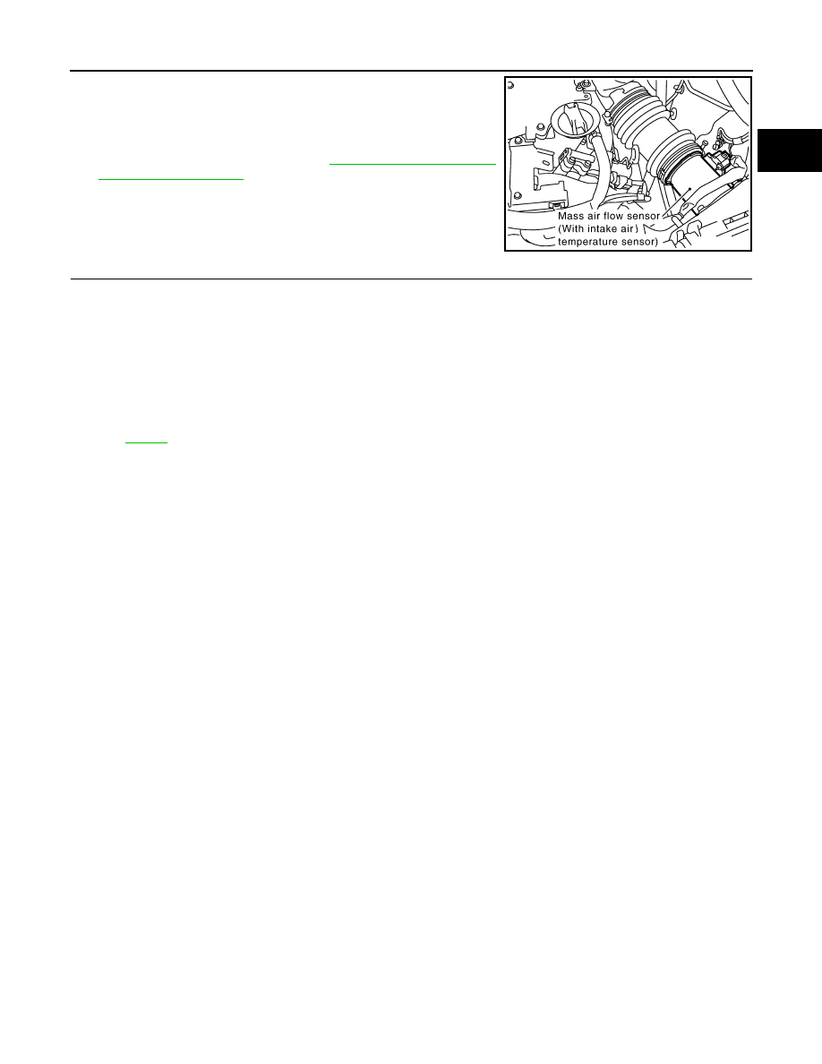
Disconnect mass air flow sensor harness connector.
4.
Restart engine and let it idle for at least 5 seconds.
5.
Stop engine and reconnect mass air flow sensor harness con-
nector.
6.
Make sure DTC P0102 is displayed.
7.
Erase the DTC memory. Refer to
8.
Make sure DTC P0000 is displayed.
>> GO TO 14.
14.
CONFIRM A/F ADJUSTMENT DATA
1.
Turn ignition switch OFF and then ON.
2.
Select “A/F ADJ-B1” and “A/F ADJ-B2” in “DATA MONITOR” mode with CONSULT-III.
3.
Make sure that “0.000” is displayed on CONSULT-III screen.
>> INSPECTION END
Removal and Installation
INFOID:0000000001326425
AIR FUEL RATIO (A/F) SENSOR 1
PBIB1565E
EC-542
< SERVICE INFORMATION >
[VQ35DE]
ASCD BRAKE SWITCH
ASCD BRAKE SWITCH
Component Description
INFOID:0000000001326426
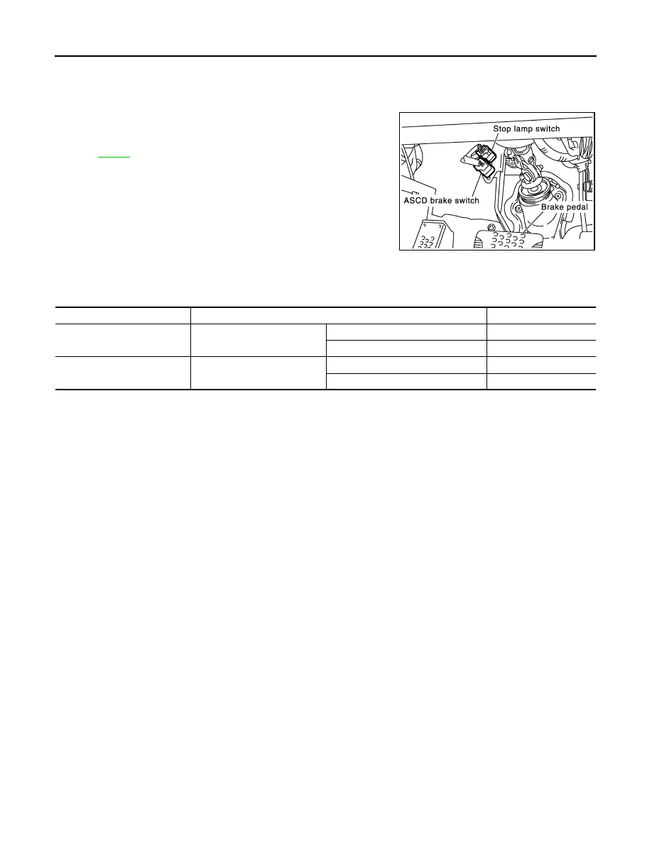
When the brake pedal is depressed, ASCD brake switch is turned
OFF and stop lamp switch is turned ON. ECM detects the state of
the brake pedal by this input of two kinds (ON/OFF signal).
Refer to
CONSULT-III Reference Value in Data Monitor Mode
INFOID:0000000001326427
Specification data are reference values.
PBIB1089E
MONITOR ITEM
CONDITION
SPECIFICATION
BRAKE SW 1
(ASCD brake switch)
• Ignition switch: ON
• Brake pedal: Fully released
ON
• Brake pedal: Slightly depressed
OFF
BRAKE SW 2
(Stop lamp switch)
• Ignition switch: ON
• Brake pedal: Fully released
OFF
• Brake pedal: Slightly depressed
ON
ASCD BRAKE SWITCH
EC-543
< SERVICE INFORMATION >
[VQ35DE]
C
D
E
F
G
H
I
J
K
L
M
A
EC
N
P
O
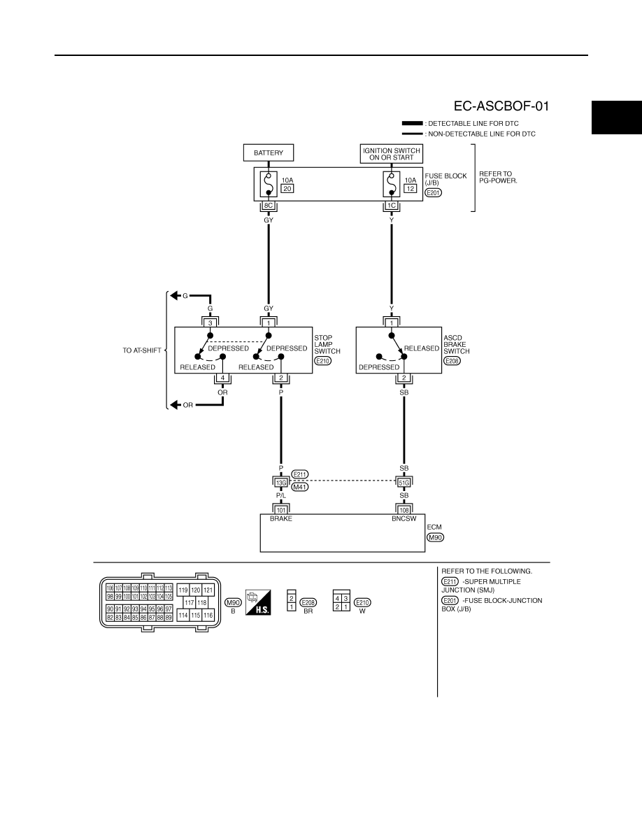
Wiring Diagram
INFOID:0000000001326428
Specification data are reference values and are measured between each terminal and ground.
CAUTION:
Do not use ECM ground terminals when measuring input/output voltage. Doing so may result in dam-
age to the ECM's transistor. Use a ground other than ECM terminals, such as the ground.
TBWM1411E
EC-544
< SERVICE INFORMATION >
[VQ35DE]
ASCD BRAKE SWITCH
Diagnosis Procedure
INFOID:0000000001326429
1.
CHECK OVERALL FUNCTION
With CONSULT-III
1.
Turn ignition switch ON.
2.
Select “BRAKE SW1” in “DATA MONITOR” mode with CONSULT-III.
3.
Check “BRAKE SW1” indication under the following conditions.
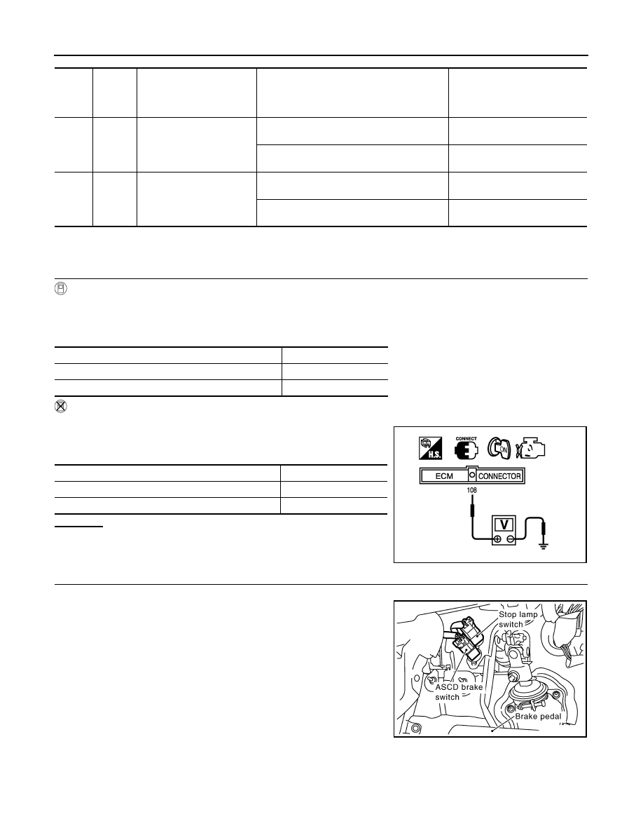
Without CONSULT-III
1.
Turn ignition switch ON.
2.
Check voltage between ECM terminal 108 and ground under the
following conditions.
OK or NG
OK
>> INSPECTION END
NG
>> GO TO 2.
2.
CHECK ASCD BRAKE SWITCH POWER SUPPLY CIRCUIT
1.
Turn ignition switch OFF.
2.
Disconnect ASCD brake switch harness connector.
3.
Turn ignition switch ON.
TER-
MI-
NAL
NO.
WIRE
COLOR
ITEM
CONDITION
DATA (DC Voltage)
101
P/L
Stop lamp switch
[Ignition switch: OFF]
• Brake pedal: Fully released
Approximately 0V
[Ignition switch: OFF]
• Brake pedal: Slightly depressed
BATTERY VOLTAGE
(11 - 14V)
108
SB
ASCD brake switch
[Ignition switch: ON]
• Brake pedal: Slightly depressed
Approximately 0V
[Ignition switch: ON]
• Brake pedal: Fully released
BATTERY VOLTAGE
(11 - 14V)
CONDITION
INDICATION
Brake pedal: Slightly depressed
OFF
Brake pedal: Fully released
ON
CONDITION
VOLTAGE
Brake pedal: Slightly depressed
Approximately 0V
Brake pedal: Fully released
Battery voltage
MBIB0061E
PBIB1605E
Нет комментариевНе стесняйтесь поделиться с нами вашим ценным мнением.
Текст