Infiniti FX35 / FX45. Manual — part 284
COMBINATION METERS
DI-11
< SERVICE INFORMATION >
C
D
E
F
G
H
I
J
L
M
A
B
DI
N
O
P
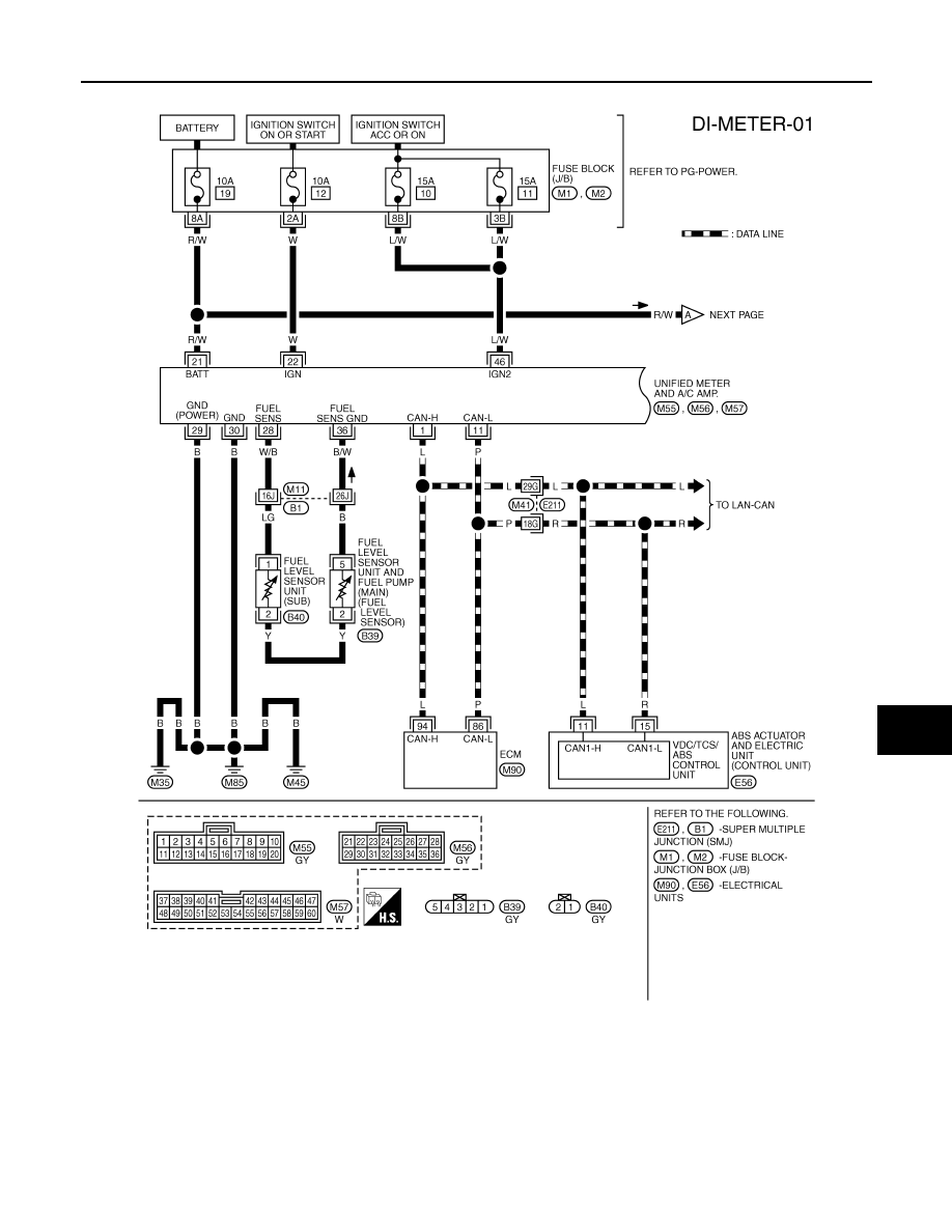
Wiring Diagram - METER -
INFOID:0000000001328437
TKWM4342E

DI-12
< SERVICE INFORMATION >
COMBINATION METERS
TKWM4343E
COMBINATION METERS
DI-13
< SERVICE INFORMATION >
C
D
E
F
G
H
I
J
L
M
A
B
DI
N
O
P
Terminal and Reference Value for Combination Meter
INFOID:0000000001328438
Terminal
No.
Wire
color
Item
Condition
Reference value
Ignition
switch
Operation or condition
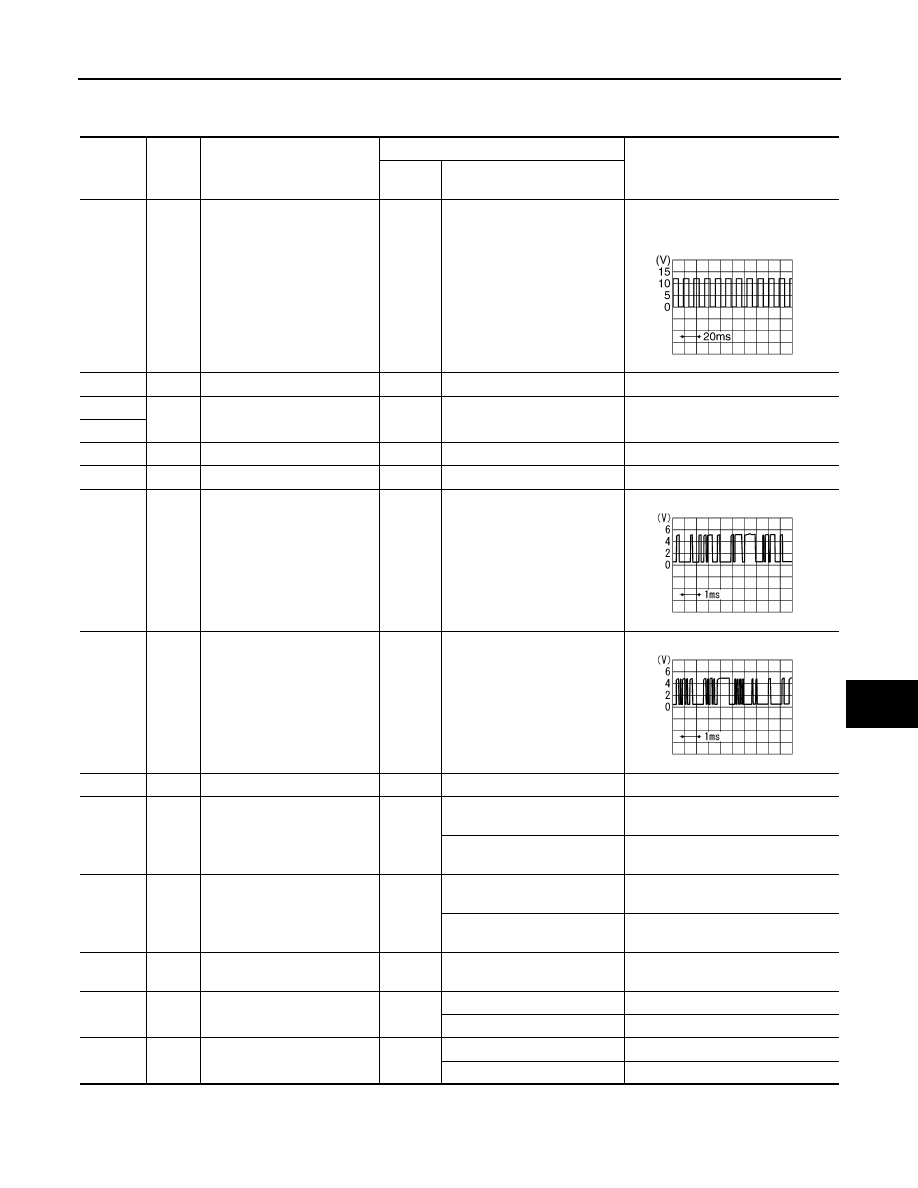
1
G
Vehicle speed signal
(8-pulse)
ON
Speedometer operated
[When vehicle speed is ap-
prox. 40 km/h (25 MPH)]
NOTE:
Maximum voltage may be 5 V due to
specifications (connected units).
4
LG
ACC power supply
ACC
—
Battery voltage
5
B
Ground
ON
—
Approx. 0 V
6
7
G/Y
Ignition power supply
ON
—
Battery voltage
8
R/W
Battery power supply
OFF
—
Battery voltage
13
L/B
TX communication line (To
unified meter and A/C amp.)
ON
—
14
PU
RX communication line (From
unified meter and A/C amp.)
ON
—
15
B
Ground
ON
—
Approx. 0 V
25
—
Illumination control switch (–)
OFF
Illumination control switch (–)
is pressed.
Approx. 0 V
Illumination control switch (–)
is released.
Approx. 5 V
26
—
Illumination control switch (+)
OFF
Illumination control switch (+)
is pressed.
Approx. 0 V
Illumination control switch (+)
is released.
Approx. 5 V
27
—
Odo/trip meter and illumina-
tion control switch ground
OFF
—
Approx. 0 V
35
—
Trip reset switch
OFF
Trip reset switch is pressed
Approx. 0 V
Trip reset switch is released
Approx. 5 V
36
—
Trip transfer switch
OFF
Trip transfer switch is pressed
Approx. 0 V
Trip transfer switch is released
Approx. 5 V
PKIA1935E
SKIA3361E
SKIA3362E
DI-14
< SERVICE INFORMATION >
COMBINATION METERS
Terminal and Reference Value for Unified Meter and A/C Amp
INFOID:0000000001328439
Self-Diagnosis Mode of Combination Meter
INFOID:0000000001328440
SELF-DIAGNOSIS FUNCTION
• Odo/trip meter, A/T indicator and ICC system display segments operation can be checked in self-diagnosis
mode.
• Meters/gauges can be checked in self-diagnosis mode.
OPERATION PROCEDURE
1.
Turn ignition switch ON, and switch the odo/trip meter to “trip A” or “trip B”.
NOTE:
If the self-diagnosis function is activated with the “trip A” displayed, only “trip A” display is reset.
2.
Turn ignition switch OFF.
Terminal
No.
Wire
color
Item
Condition
Reference value
Ignition
switch
Operation or condition
1
L
CAN-H
—
—
—
9
PU
TX communication line (To
combination meter)
ON
—
11
P
CAN-L
—
—
—
19
L/B
RX communication line (From
combination meter)
ON
—
21
R/W
Battery power supply
OFF
—
Battery voltage
22
W
Ignition power supply
ON
—
Battery voltage
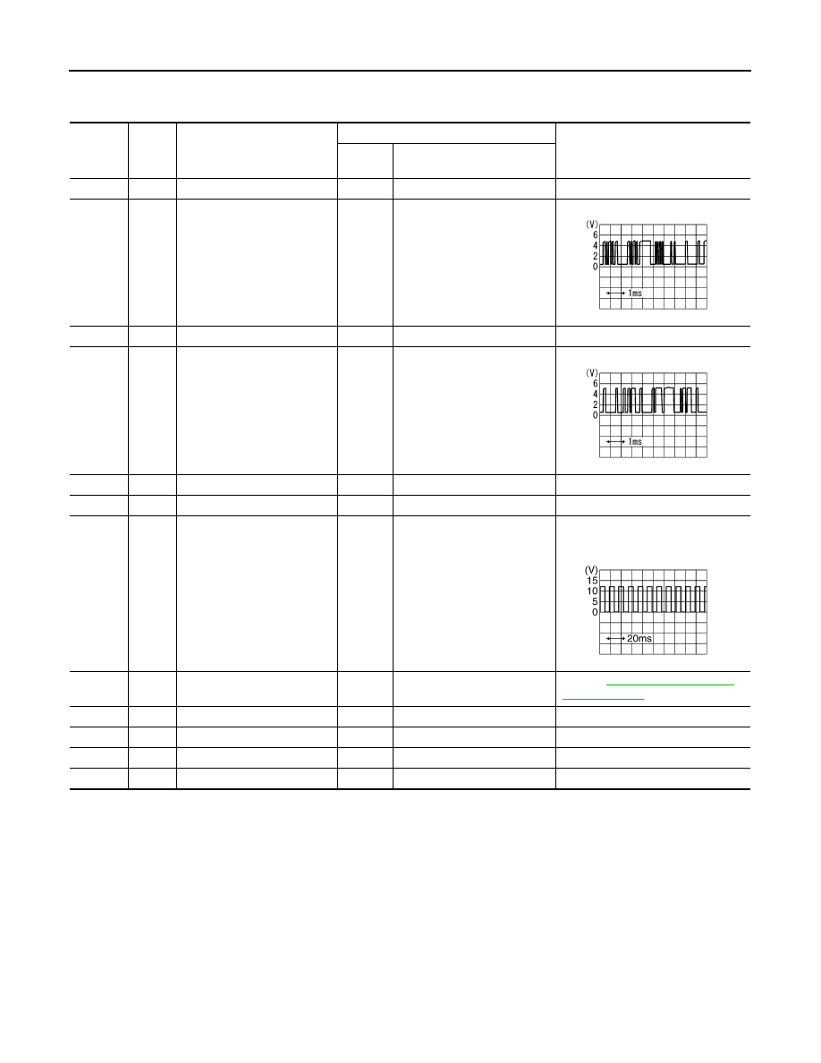
26
G
Vehicle speed signal
(8-pulse)
ON
Speedometer operated
[When vehicle speed is ap-
prox. 40 km/h (25 MPH)]
NOTE:
Maximum voltage may be 5 V due to
specifications (connected units).
28
W/B
Fuel level sensor signal
—
—
Refer to
.
29
B
Ground (For power)
ON
—
Approx. 0 V
30
B
Ground
ON
—
Approx. 0 V
36
B/W
Fuel level sensor ground
ON
—
Approx. 0 V
46
L/W
ACC power supply
ACC
—
Battery voltage
SKIA3362E
SKIA3361E
PKIA1935E
Нет комментариевНе стесняйтесь поделиться с нами вашим ценным мнением.
Текст