Infiniti FX35 / FX45. Manual — part 285
COMBINATION METERS
DI-15
< SERVICE INFORMATION >
C
D
E
F
G
H
I
J
L
M
A
B
DI
N
O
P
3.
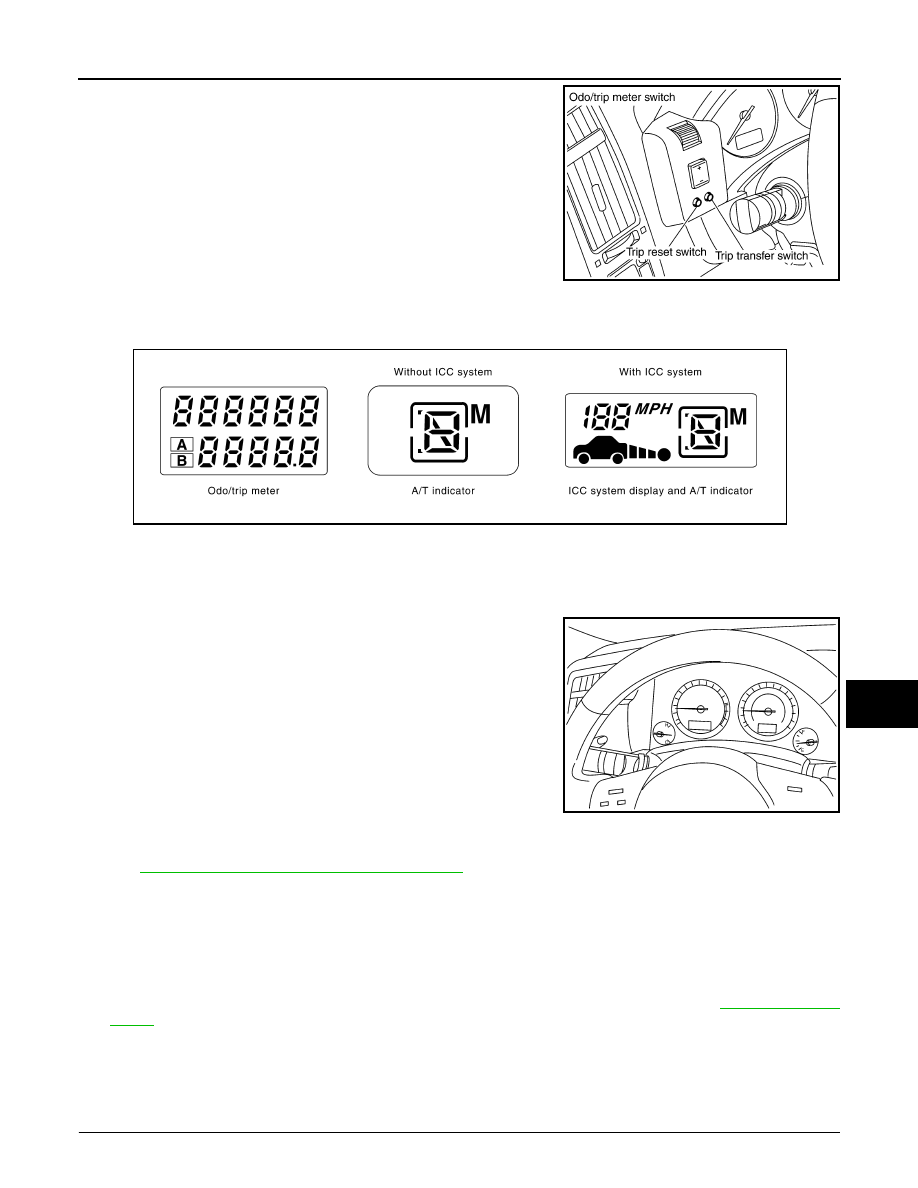
Turn ignition switch ON while pressing trip transfer switch and
trip reset switch at the same time.
4.
After ignition switch is turned ON, release trip transfer switch
and trip reset switch (within 7 seconds after the ignition switch is
turned ON).
5.
All the segments on the odo/trip meter, A/T indicator and ICC system display illuminates, and simulta-
neously the low-fuel warning lamp indicator illuminates. At this time, the unified meter control unit is turned
to self-diagnosis mode.
NOTE:
• Check odo/trip meter switch and combination meter power supply and ground circuit when self-diagno-
sis mode of combination meter does not start. Replace combination meter if the results of the check are
normal.
• If any of the segments are not displayed, replace combination meter.
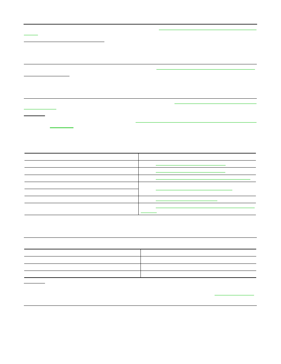
6.
Each meter/gauge activates during pressing trip reset switch.
(Then low-fuel warning lamp turns OFF.)
NOTE:
• If any of the meters/gauges are not activated, replace the
combination meter.
• The figure is reference.
CONSULT-III Function (METER/M&A)
INFOID:0000000001328441
DI-27, "CONSULT-III Function (METER/M&A)"
in “UNIFIED METER AND A/C AMP”.
Trouble Diagnosis
INFOID:0000000001328442
HOW TO PERFORM TROUBLE DIAGNOSIS
1.
Confirm the symptom or customer complaint.
2.
Perform preliminary check. Refer to "PRELIMINARY CHECK".
3.
According to the symptom chart, repair or replace the cause of the symptom. Refer to
4.
Does the meter operate normally? If so, GO TO 5. If not, GO TO 2.
5.
INSPECTION END
PRELIMINARY CHECK
1.
CHECK OPERATION OF SELF-DIAGNOSIS MODE (COMBINATION METER)
SKIA4817E
SKIA6170E
SKIA4831E
DI-16
< SERVICE INFORMATION >
COMBINATION METERS
Perform self-diagnosis mode of combination meter. Refer to
DI-14, "Self-Diagnosis Mode of Combination
Does self-diagnosis function operate?
YES
>> GO TO 2.
NO
>> GO TO 3.
2.
CHECK UNIFIED METER AND A/C AMP. (CONSULT-III)
Perform self-diagnosis of unified meter and A/C amp. Refer to
DI-27, "CONSULT-III Function (METER/M&A)"
.
Self-diagnosis results
No malfunction detected >> INSPECTION END
Malfunction detected >> Check applicable parts, and repair or replace corresponding parts.
3.
CHECK POWER SUPPLY AND GROUND CIRCUIT OF COMBINATION METER
Check power supply and ground circuit of combination meter. Refer to
DI-16, "Power Supply and Ground Cir-
.
OK or NG
OK
>> Check odo/trip meter switch. Refer to
DI-21, "Odo/Trip Meter and Illumination Control Switch
.
NG
>> Repair malfunctioning part.
Symptom Chart
INFOID:0000000001328443
Power Supply and Ground Circuit Inspection
INFOID:0000000001328444
1.
CHECK FUSE
Check for blown combination meter fuses.
OK or NG
OK
>> GO TO 2.
NG
>> Be sure to eliminate cause of malfunction before installing new fuse. Refer to
.
2.
CHECK POWER SUPPLY CIRCUIT
Symptom
Possible cause
Speedometer and odo/trip meter indication is malfunctioning.
Refer to
DI-17, "Vehicle Speed Signal Inspection"
.
Tachometer indication is malfunctioning.
Refer to
DI-18, "Engine Speed Signal Inspection"
Water temperature gauge indication is malfunctioning.
Refer to
DI-19, "Engine Coolant Temperature Signal Inspection"
.
Fuel gauge indication is malfunctioning.
Refer to
DI-19, "Fuel Level Sensor Signal Inspection"
Low-fuel warning lamp indication is irregular.
A/T indicator is malfunctioning.
Refer to
DI-49, "A/T Indicator Is Malfunction"
.
Illumination control does not operate.
Refer to
DI-21, "Odo/Trip Meter and Illumination Control Switch In-
.
Power source
Fuse No.
Battery power supply
19
ACC power supply
6
Ignition power supply
14
COMBINATION METERS
DI-17
< SERVICE INFORMATION >
C
D
E
F
G
H
I
J
L
M
A
B
DI
N
O
P
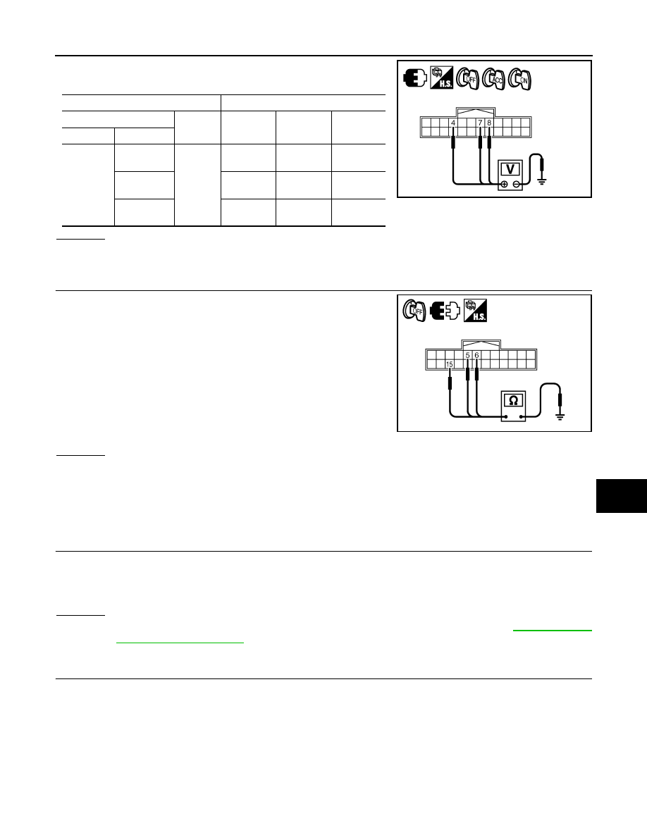
Check voltage between combination meter harness connector M20
terminals 4, 7, 8 and ground.
OK or NG
OK
>> GO TO 3.
NG
>> Check harness between combination meter and fuse.
3.
CHECK GROUND CIRCUIT
1.
Turn ignition switch OFF.
2.
Disconnect combination meter connector.
3.
Check continuity between combination meter harness connector
M20 terminals 5, 6, 15 and ground.
OK or NG
OK
>> INSPECTION END
NG
>> Repair harness or connector.
Vehicle Speed Signal Inspection
INFOID:0000000001328445
Symptom: Speedometer and odo/trip meter indication is malfunction.
1.
CHECK COMBINATION METER INPUT SIGNAL
1.
Connect CONSULT-III, and start engine.
2.
Select “METER /M&A” on CONSULT-III.
3.
Using “SPEED METER” on “Data Monitor”, compare the value of “Data Monitor” with speedometer pointer
of combination meter.
OK or NG
OK
>> Perform self-diagnosis of ABS actuator and electric unit (control unit). Refer to
NG
>> GO TO 2.
2.
CHECK UNIFIED METER AND A/C AMP. OUTPUT SIGNAL
1.
Drive vehicle at approximately 40 km/h (25 MPH).
Terminals
Ignition switch position
(+)
(–)
OFF
ACC
ON
Connector
Terminal
M20
4
Ground
0 V
Battery
voltage
Battery
voltage
7
0 V
0 V
Battery
voltage
8
Battery
voltage
Battery
voltage
Battery
voltage
SKIB8525E
5 – Ground
: Continuity should exist.
6 – Ground
15 – Ground
SKIB8526E
DI-18
< SERVICE INFORMATION >
COMBINATION METERS
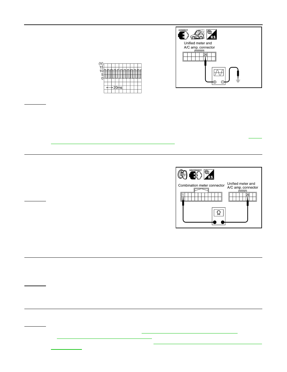
2.
Check voltage signal between unified meter and A/C amp. har-
ness connector M56 terminal 26 and ground.
OK or NG
OK
>> GO TO 3.
NG-1
>>
If monitor indicates “0 V” constantly, perform the following.
1.
Check each unit inputting vehicle speed signal (8 pulse), harness and connector between
each unit and unified meter and A/C amp.
2.
Repair or replace malfunctioning part.
NG-2
>> If monitor indicates “5 V” or “12 V” constantly, replace unified meter and A/C amp. Refer to
"Removal and Installation of Unified Meter and A/C Amp"
.
3.
CHECK CONTINUITY BETWEEN COMBINATION METER AND UNIFIED METER AND A/C AMP.
1.
Turn ignition switch OFF.
2.
Disconnect combination meter connector and unified meter and A/C amp. connector.
3.
Check continuity between combination meter harness connector
M20 terminal 1 and unified meter and A/C amp. harness con-
nector M56 terminal 26.
OK or NG
OK
>> Replace combination meter.
NG
>> Repair harness or connector.
Engine Speed Signal Inspection
INFOID:0000000001328446
Symptom: Tachometer indication is malfunction.
1.
CHECK COMBINATION METER INPUT SIGNAL
1.
Connect CONSULT-III, and start engine.
2.
Select “METER/M&A” on CONSULT-III.
3.
Using “TACHO METER” on “Data Monitor”, compare the value of “Data Monitor” with tachometer pointer
of combination meter.
OK or NG
OK
>> GO TO 2.
NG
>> Replace combination meter.
2.
CHECK UNIFIED METER AND A/C AMP. INPUT SIGNAL
Select “Data Monitor” of CONSULT-III to compare values between “ ENG SPEED” of “ENGINE” and “TACHO
METER” of “METER/M&A”.
OK or NG
OK
>> Perform self-diagnosis of ECM. Refer to
EC-117, "CONSULT-III Function (ENGINE)"
or
EC-695, "CONSULT-III Function (ENGINE)"
NG
>> Replace unified meter and A/C amp. Refer to
DI-32, "Removal and Installation of Unified Meter
.
26 – Ground:
NOTE:
Maximum voltage may be 5 V due to
specifications (connected units).
SKIB0338E
PKIA1935E
1 – 26
: Continuity should exist.
SKIB0343E
Нет комментариевНе стесняйтесь поделиться с нами вашим ценным мнением.
Текст