Infiniti FX35 / FX45. Manual — part 929
SE-74
< SERVICE INFORMATION >
AUTOMATIC DRIVE POSITIONER
3.
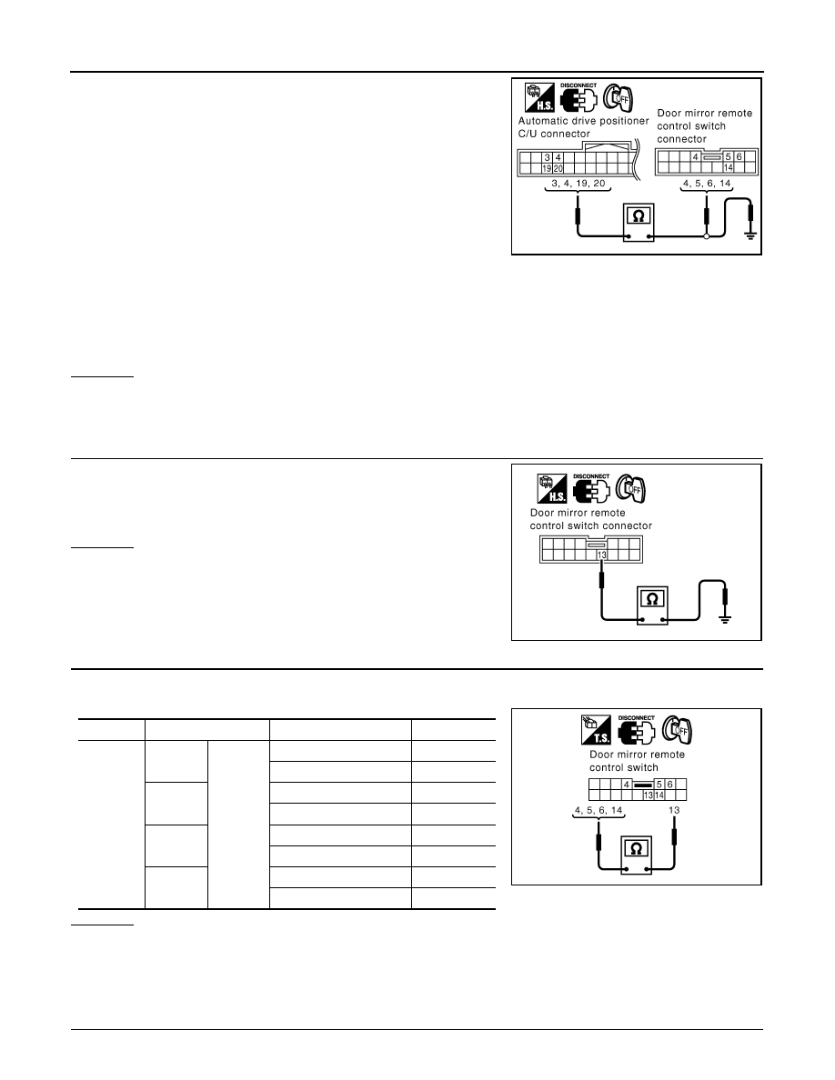
Check continuity between automatic drive positioner control unit
connector M49 terminal 3, 4, 19, 20 and door mirror remote con-
trol switch connector M18 terminal 4, 5, 6, 14.
4.
Check continuity between automatic drive positioner control unit
connector M49 terminal 3, 4, 19, 20 and ground.
OK or NG
OK
>> GO TO 4.
NG
>> Repair or replace harness between automatic drive positioner control unit and door mirror remote
control switch.
3.
CHECK DOOR MIRROR REMOTE CONTROL SWITCH GROUND CIRCUIT
Check continuity between door mirror remote control switch connec-
tor M18 terminal 13 and ground.
OK or NG
OK
>> GO TO 4.
NG
>> Repair or replace harness.
4.
CHECK DOOR MIRROR REMOTE CONTROL SWITCH (MIRROR SWITCH)
Mirror switch operate, check continuity between door mirror remote control switch connector M18 terminal 4,
5, 6, 14 and 13.
OK or NG
OK
>> Check the condition of the harness and the connector.
NG
>> Replace door mirror remote control switch.
Check A/T Device (Park Position Switch) Circuit
INFOID:0000000001328138
1.
CHECK FUNCTION
3 (GY) – 6 (GY)
: Continuity should exist.
4 (Y) – 5 (Y)
: Continuity should exist.
19 (GY/L) – 14 (GY/L)
: Continuity should exist.
20 (PU) – 4 (PU)
: Continuity should exist.
3 (GY) – Ground
: Continuity should not exist.
4 (Y) – Ground
: Continuity should not exist.
19 (GY/L) – Ground
: Continuity should not exist.
20 (PU) – Ground
: Continuity should not exist.
PIIB3168E
13 (B) – Ground
: Continuity should exist.
PIIB3166E
Connector
Terminal
Mirror switch condition
Continuity
M18
4
13
RIGHT
Yes
Other than above
No
5
LEFT
Yes
Other than above
No
6
UP
Yes
Other than above
No
14
DOWN
Yes
Other than above
No
PIIB3169E
AUTOMATIC DRIVE POSITIONER
SE-75
< SERVICE INFORMATION >
C
D
E
F
G
H
J
K
L
M
A
B
SE
N
O
P
With CONSULT-III
Make sure when the A/T selector lever is in P position, “P POSI SW” on the DATA MONITOR becomes ON.
Without CONSULT-III
1.
Turn ignition switch OFF.
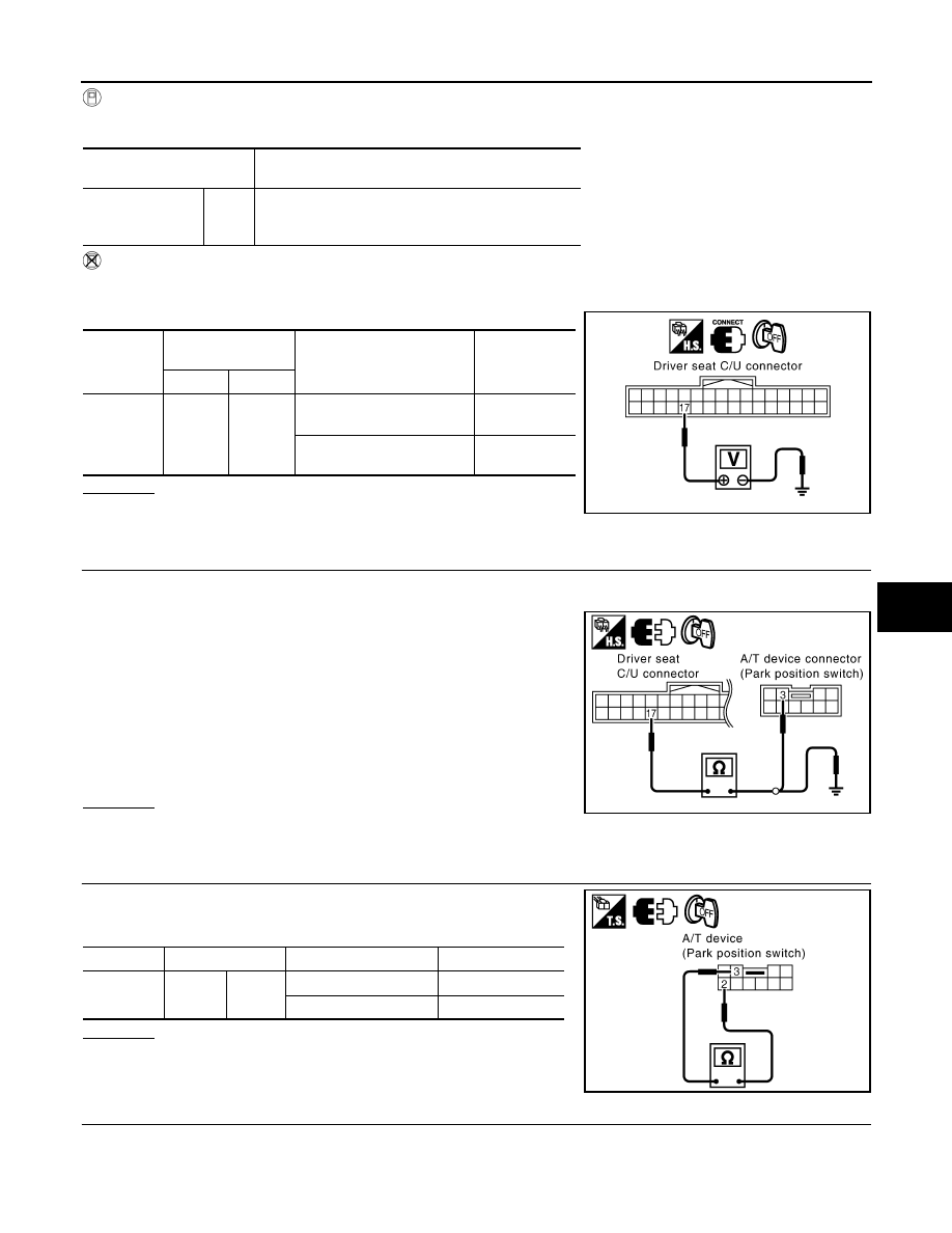
2.
Check voltage between drive seat control unit connector and ground.
OK or NG
OK
>> Park position switch circuit is OK.
NG
>> GO TO 2.
2.
CHECK PARK POSITION SWITCH POWER SUPPLY CIRCUIT HARNESS
1.
Turn ignition switch OFF.
2.
Disconnect driver seat control unit connector and A/T device (park position switch) connector.
3.
Check continuity between driver seat control unit connector
B152 terminal 17 and A/T device (park position switch) connec-
tor M67 terminal 3.
4.
Check continuity between driver seat control unit connector
B152 terminal 17 and ground.
OK or NG
OK
>> GO TO 3.
NG
>> Repair or replace harness between driver seat control unit and A/T device (park position switch).
3.
CHECK A/T DEVICE (PARK POSITION SWITCH)
Check continuity between A/T device (park position switch) connec-
tor M67 terminal 2 and 3.
OK or NG
OK
>> GO TO 4.
NG
>> Replace A/T device (park position switch).
4.
CHECK A/T DEVICE (PARK POSITION SWITCH) GROUND HARNESS
Monitor item
[OPERATION or UNIT]
Contents
P POSI SW
“ON/
OFF”
The selector lever position “P position (ON)/other than
P position (OFF)” judged from the park position switch
signal is displayed.
Connector
Terminals
(Wire color)
Condition
Voltage (V)
(Approx.)
(+)
(–)
B152
17 (PU)
Ground
Selector lever sifted to P po-
sition.
0
Selector lever other than P
position.
Battery voltage
PIIA6702E
17 (PU) – 3 (R/Y)
: Continuity should exist.
17 (PU) – Ground
: Continuity should not exist.
PIIB9068E
Connector
Terminal
Condition
Continuity
M67
2
3
P position
Yes
Other than P position
No
PIIB9069E
SE-76
< SERVICE INFORMATION >
AUTOMATIC DRIVE POSITIONER
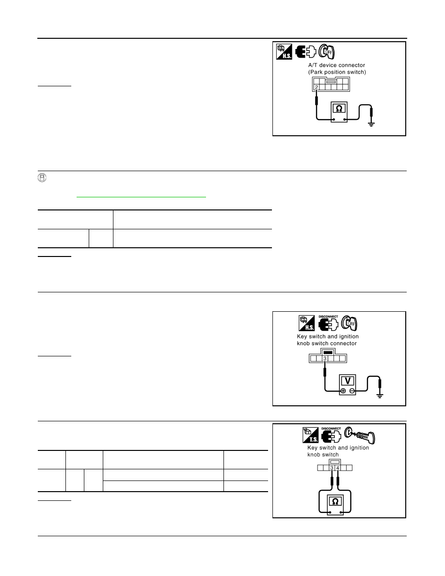
Check continuity between A/T device (park position switch) connec-
tor M67 terminal 2 and ground.
OK or NG
OK
>> Check the condition of the harness and connector.
NG
>> Repair or replace harness between A/T device (park
position switch) and ground.
Check Key Switch Circuit (With Intelligent Key)
INFOID:0000000001328139
1.
CHECK KEY SWITCH POWER SUPPRY CIRCUIT
With CONSULT-III
Touch “BCM”. With “IGN KEY SW” on the DATA MONITOR, Check ON/OFF operation.
*: Refer to
BL-36, "CONSULT-III Function (BCM)"
.
OK or NG
OK
>> Key switch circuit is OK.
NG
>> GO TO 2.
2.
CHECK KEY SWITCH POWER SUPPLY CIRCUIT
1.
Turn ignition switch OFF.
2.
Disconnect key switch and ignition knob switch connector.
3.
Check voltage between key switch and ignition knob switch con-
nector M22 terminal 3 and ground.
OK or NG
OK
>> GO TO 3.
NG
>> Check harness between key switch and fuse.
3.
CHECK KEY SWITCH
Check continuity between key switch and ignition knob switch con-
nector M22 terminal 3 and 4.
OK or NG
OK
>> GO TO 4.
NG
>> Replace key switch and ignition knob switch.
4.
CHECK HARNESS CONTINUITY
1.
Disconnect key switch and ignition knob switch connector and BCM connector.
2 (B) – Ground
: Continuity should exist.
PIIB9071E
Monitor item [OPERA-
TION or UNIT]
Contents
IGN KEY SW
*
“ON/
OFF”
Key inserted (ON)/key removed (OFF) status judged
from the key-in detection switch is displayed.
3 (L/R) – Ground
: Battery voltage.
PIIA5093E
Con-
nector
Terminal
Condition
Continuity
M22
3
4
Key is inserted in ignition key cylinder.
Yes
Key is removed from ignition key cylinder.
No
PIIA6140E
AUTOMATIC DRIVE POSITIONER
SE-77
< SERVICE INFORMATION >
C
D
E
F
G
H
J
K
L
M
A
B
SE
N
O
P
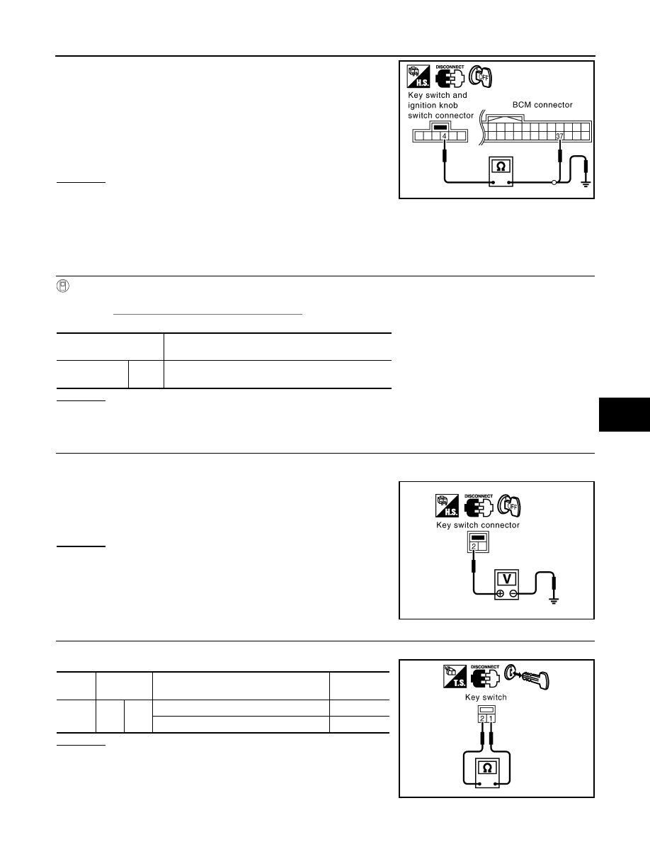
2.
Check continuity between key switch and ignition knob switch
connector M22 terminal 4 and BCM connector M3 terminal 37.
3.
Check continuity between key switch and ignition knob switch
connector M22 terminal 4 and ground.
OK or NG
OK
>> Key switch circuit is OK.
NG
>> Repair or replace harness between key switch and igni-
tion knob switch and BCM.
Check Key Switch Circuit (Without Intelligent Key)
INFOID:0000000001328140
1.
CHECK KEY SWITCH
With CONSULT-III
Touch “BCM”. With “IGN KEY SW” on the DATA MONITOR, Check ON/OFF operation.
*: Refer to
BL-36, "CONSULT-III Function (BCM)"
OK or NG
OK
>> Key switch circuit is OK.
NG
>> GO TO 2.
2.
CHECK KEY SWITCH AND KEY LOCK SOLENOID POWER SUPPLY CIRCUIT
1.
Turn ignition switch OFF.
2.
Disconnect key switch connector.
3.
Check voltage between key switch connector M23 terminal 2
and ground.
OK or NG
OK
>> GO TO 3.
NG
>> Check harness between key switch and fuse.
3.
CHECK KEY SWITCH
Check continuity between key switch connector M23 terminal 1 and 2.
OK or NG
OK
>> GO TO 4.
NG
>> Replace key switch.
4 (B/W) – 37 (B/W)
: Continuity should exist.
4 (B/W) – Ground
: Continuity should not exist.
PIIA5095E
Monitor item
[OPERATION or UNIT]
Contents
IGN KEY SW
*
“ON/
OFF”
Key inserted (ON)/key removed (OFF) status judged
from the key-in detection switch is displayed.
2 (L/R) – Ground
: Battery voltage.
PIIA5092E
Con-
nector
Terminal
Condition
Continuity
M23
1
2
Key is inserted in ignition key cylinder.
Yes
Key is removed from ignition key cylinder.
No
PIIA6141E
Нет комментариевНе стесняйтесь поделиться с нами вашим ценным мнением.
Текст