Infiniti FX35 / FX45. Manual — part 928
SE-70
< SERVICE INFORMATION >
AUTOMATIC DRIVE POSITIONER
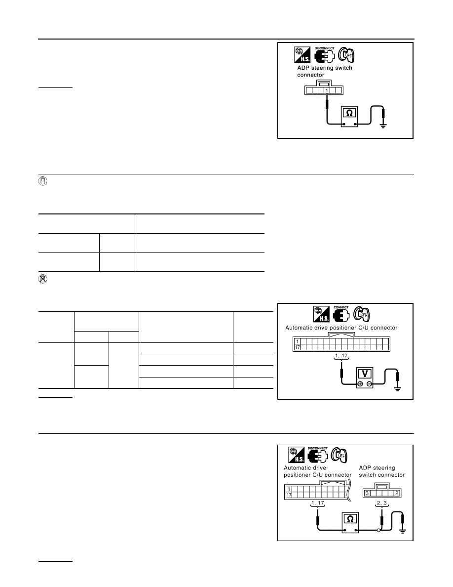
Check continuity between ADP steering switch connector M13 termi-
nal 1 and ground.
OK or NG
OK
>> Check the condition of the harness and connector.
NG
>> Replace or replace harness between ADP steering
switch and ground.
Check Tilt Switch Circuit
INFOID:0000000001328135
1.
CHECK FUNCTION
With CONSULT-III
With “TILT SW-UP, TILT SW-DOWN” on the DATA MONITOR, operate the ADP steering switch to check ON/
OFF operation.
Without CONSULT-III
1.
Turn ignition switch OFF.
2.
Tilt switch operate, check voltage between automatic drive positioner control unit connector and ground.
OK or NG
OK
>> Tilt switch circuit is OK.
NG
>> GO TO 2.
2.
CHECK TILT SWITCH CIRCUIT HARNESS CONTINUITY
1.
Disconnect automatic drive positioner control unit connector and ADP steering switch connector.
2.
Check continuity between automatic drive positioner control unit
connector M49 terminals 1, 17 and ADP steering switch connec-
tor M13 terminals 2, 3.
3.
Check continuity between automatic drive positioner control unit
connector M49 terminals 1, 17 and ground.
OK or NG
1 (B) – Ground
: Continuity should exist.
PIIA3308E
Monitor item
[OPERATION or UNIT]
Contents
TILT SW-UP
“ON/OFF”
(ON/OFF) status judged from the tilt switch
(UP) signal is displayed.
TILT SW-DOWN
“ON/OFF”
(ON/OFF) status judged from the tilt switch
(DOWN) signal is displayed.
Connector
Terminals
(Wire color)
Tilt switch condition
Voltage (V)
(Approx.)
(+)
(–)
M49
1 (R)
Ground
UP
0
Other than above
5
17 (R/B)
DOWN
0
Other than above
5
PIIA5074E
1 (R) – 2 (R)
: Continuity should exist.
17 (R/B) – 3 (R/B)
: Continuity should exist.
1 (R) – Ground
: Continuity should not exist.
17 (R/B) – Ground
: Continuity should not exist.
PIIA5072E
AUTOMATIC DRIVE POSITIONER
SE-71
< SERVICE INFORMATION >
C
D
E
F
G
H
J
K
L
M
A
B
SE
N
O
P
OK
>> GO TO 3.
NG
>> Repair or replace harness between automatic drive positioner control unit and ADP steering
switch.
3.
CHECK ADP TILT STEERING SWITCH
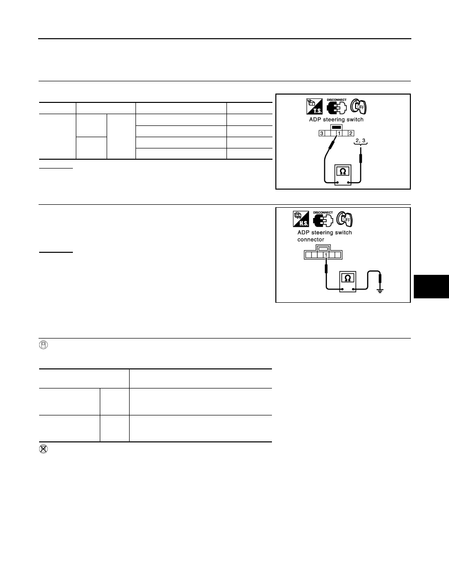
ADP steering switch operate, check continuity between ADP steering switch.
OK or NG
OK
>> GO TO 6.
NG
>> Replace ADP steering switch.
4.
CHECK ADP STEERING SWITCH GROUND CIRCUIT
Check continuity between ADP steering switch connector M13 termi-
nal 1 and ground.
OK or NG
OK
>> Check the condition of the harness and connector.
NG
>> Repair or replace harness between ADP steering switch
and ground.
Check Door Mirror Remote Control Switch (Changeover Switch) Circuit
INFOID:0000000001328136
1.
CHECK FUNCTION
With CONSULT-III
Check the operation on “MIR CHNG SW-R” or “MIR CHNG SW-L” in the DATA MONITOR.
Without CONSULT-III
1.
Turn ignition switch ACC.
2.
Changeover switch operate, check voltage between automatic drive positioner control unit connector and
ground.
Connector
Terminal
ADP steering switch condition
Continuity
M13
2
1
UP
Yes
Other than above
No
3
DOWN
Yes
Other than above
No
PIIA4482E
1 (B) – Ground
: Continuity should exist.
PIIA3310E
Monitor item
[OPERATION or UNIT]
Contents
MIR CHNG SW–R
“ON/
OFF”
ON/OFF status judged from the door mirror re-
mote control switch (switching to RIGHT) signal is
displayed.
MIR CHNG SW–L
“ON/
OFF”
ON/OFF status judged from the door mirror re-
mote control switch (switching to LEFT) signal is
displayed.
SE-72
< SERVICE INFORMATION >
AUTOMATIC DRIVE POSITIONER
OK or NG
OK
>> Door mirror remote control switch (changeover switch)
circuit is OK.
NG
>> GO TO 2.
2.
CHECK CHANGEOVER SWITCH CIRCUIT HARNESS CONTINUITY
1.
Turn ignition switch OFF.
2.
Disconnect automatic drive positioner control unit and door mirror remote control switch connector.
3.
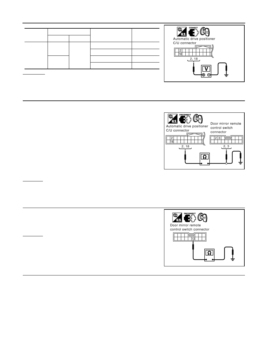
Check continuity between automatic drive positioner control unit
connector M49 terminal 2, 18 and door mirror remote control
switch connector M18 terminal 2, 3.
4.
Check continuity between automatic drive positioner control unit
connector M49 terminal 2, 18 and ground.
OK or NG
OK
>> GO TO 3.
NG
>> Repair or replace harness between automatic drive positioner control unit and door remote control
switch.
3.
CHECK DOOR MIRROR REMOTE CONTROL SWITCH GROUND CIRCUIT
Check continuity between door mirror remote control switch connec-
tor M18 terminal 13 and ground.
OK or NG
OK
>> GO TO 4.
NG
>> Repair or replace harness.
4.
CHECK DOOR MIRROR REMOTE CONTROL SWITCH (CANGEOVER SWITCH)
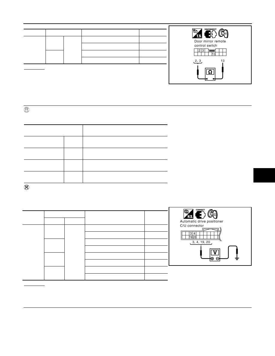
Changeover switch operate, check continuity between door mirror remote control switch connector M18 termi-
nal 2, 3 and 13.
Connector
Terminals (Wire color)
Changeover switch
condition
Voltage (V)
(Approx.)
(+)
(-)
M49
2 (G/W)
Ground
RIGHT
0
Other than above
5
18 (L/OR)
LEFT
0
Other than above
5
PIIA4767E
2 (G/W) – 3 (G/W)
: Continuity should exist.
18 (L/OR) – 2 (L/OR)
: Continuity should exist.
2 (G/W) – Ground
: Continuity should not exist.
18 (L/OR) – Ground
: Continuity should not exist.
PIIB3165E
13 (B) – Ground
: Continuity should exist.
PIIB3166E
AUTOMATIC DRIVE POSITIONER
SE-73
< SERVICE INFORMATION >
C
D
E
F
G
H
J
K
L
M
A
B
SE
N
O
P
OK or NG
OK
>> Check the condition of the harness and the connector.
NG
>> Replace door mirror remote control switch.
Check Door Mirror Remote Control Switch (Mirror Switch) Circuit
INFOID:0000000001328137
1.
CHECK DOOR MIRROR REMOTE CONTROL SWITCH (MIRROR SWITCH) SIGNAL
With CONSULT-III
Check the operation on “MIR CON SW–UP/DN” and “MIR CON SW–RH/LH” in the DATA MONITOR.
Without CONSULT-III
1.
Turn ignition switch ACC.
2.
Mirror switch operate, check voltage between automatic drive positioner control unit connector and
ground.
OK or NG
OK
>> Door mirror remote control switch (mirror switch) circuit is OK.
NG
>> GO TO 2.
2.
CHECK HARNESS CONTINUITY
1.
Turn ignition switch OFF.
2.
Disconnect automatic drive positioner control unit and door mirror remote control switch connector.
Connector
Terminal
Changeover switch condition
Continuity
M18
3
13
RIGHT
Yes
Other than above
No
2
LEFT
Yes
Other than above
No
PIIB3167E
Monitor item
[OPERATION or UNIT]
Contents
MIR CON SW–UP
“ON/
OFF”
ON/OFF status judged from the door mirror re-
mote control switch (UP) signal is displayed.
MIR CON SW–DN
“ON/
OFF”
ON/OFF status judged from the door mirror re-
mote control switch (DOWN) signal is displayed.
MIR CON SW–RH
“ON/
OFF”
ON/OFF status judged from the door mirror re-
mote control switch (RIGHT) signal is displayed.
MIR CON SW–LH
“ON/
OFF”
ON/OFF status judged from the door mirror re-
mote control switch (LEFT) signal s displayed.
Connector
Terminals (Wire color)
Mirror switch condition
Voltage (V)
(Approx.)
(+)
(-)
M49
3 (GY)
Ground
UP
0
Other than above
5
4 (Y)
LEFT
0
Other than above
5
19 (GY/L)
DOWN
0
Other than above
5
20 (PU)
RIGHT
0
Other than above
5
PIIA4771E
Нет комментариевНе стесняйтесь поделиться с нами вашим ценным мнением.
Текст