Infiniti FX35 / FX45. Manual — part 927
SE-66
< SERVICE INFORMATION >
AUTOMATIC DRIVE POSITIONER
Check Front Lifting Switch Circuit
INFOID:0000000001328131
1.
CHECK FUNCTION
With CONSULT-III
With “LIFT FR SW-UP, LIFT FR SW-DN” on the DATA MONITOR, operate the front lifting switch to check ON/
OFF operation.
Without CONSULT-III
1.
Turn ignition switch OFF.
2.
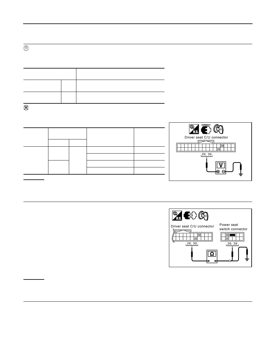
Front lifting switch operate, check voltage between driver seat control unit connector and ground.
OK or NG
OK
>> Front lifting switch circuit is OK.
NG
>> GO TO 2.
2.
CHECK HARNESS CONTINUITY
1.
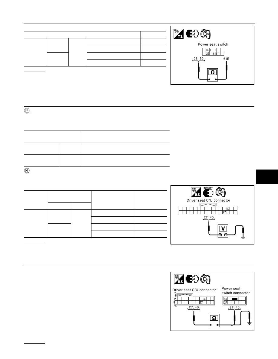
Disconnect driver seat control unit connector and power seat switch connector.
2.
Check continuity between driver seat control unit connector
B152 terminals 26, 39 and power seat switch connector B175
terminals 26, 39.
3.
Check continuity between driver seat control unit connector
B152 terminals 26, 39 and ground
OK or NG
OK
>> GO TO 3.
NG
>> Repair or replace harness between driver seat control unit and power seat switch.
3.
CHECK FRONT LIFTING SWITCH
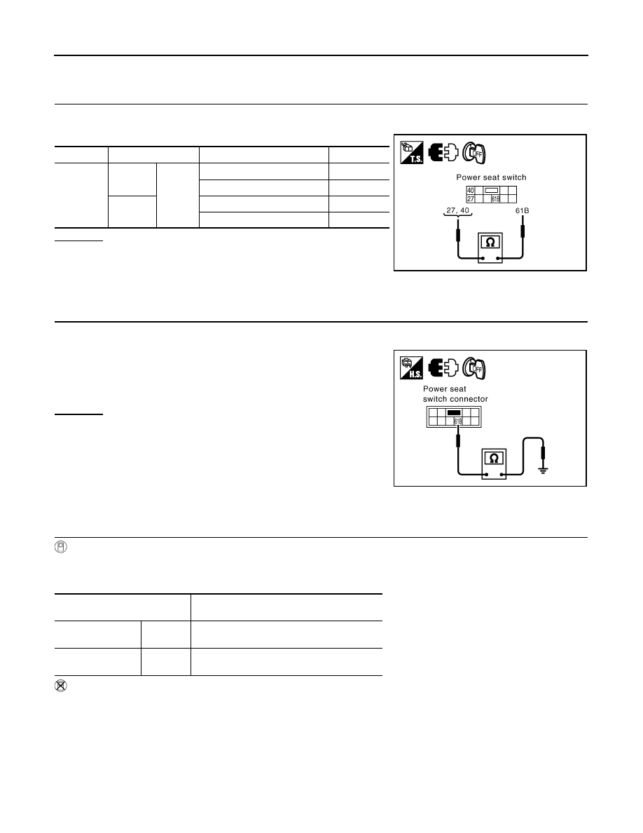
Front lifting switch operate, check continuity between power seat switch connector B175 terminal 26, 39 and
61B.
Monitor item
[OPERATION or UNIT]
Contents
LIFT FR SW – DN
“ON/
OFF”
ON/OFF status judged from the FR lifter switch
(DOWN) signal is displayed.
LIFT RR SW – UP
“ON/
OFF”
ON/OFF status judged from the RR lifter switch
(UP) signal is displayed.
Connector
Terminals
(Wire color)
Front lifting switch
condition
Voltage (V) (Ap-
prox.)
(+)
(–)
B152
26 (L/P)
Ground
UP
0
Other than above
Battery voltage
39 (L/G)
DOWN 0
Other than above
Battery voltage
PIIA6097E
26 (L/P) – 26 (L/P)
: Continuity should exist.
39 (L/G) – 39 (L/G)
: Continuity should exist.
26 (L/P) – Ground
: Continuity should not exist.
39 (L/G) – Ground
: Continuity should not exist.
PIIB8593E
AUTOMATIC DRIVE POSITIONER
SE-67
< SERVICE INFORMATION >
C
D
E
F
G
H
J
K
L
M
A
B
SE
N
O
P
OK or NG
OK
>> Check the condition of the harness and connector.
NG
>> Replace power seat switch.
Check Rear Lifting Switch Circuit
INFOID:0000000001328132
1.
CHECK FUNCTION
With CONSULT-III
With “LIFT RR SW-UP, LIFT RR SW-DN” on the DATA MONITOR, operate the rear lifting switch to check ON/
OFF operation.
Without CONSULT-III
1.
Turn ignition switch OFF.
2.
Rear lifting switch operate, check voltage between driver seat control unit connector and ground.
OK or NG
OK
>> Rear seat lifting switch circuit is OK.
NG
>> GO TO 2.
2.
CHECK REAR LIFTING SWITCH HARNESS CONTINUITY
1.
Disconnect driver seat control unit connector and power seat switch connector.
2.
Check continuity between driver seat control unit connector
B152 terminals 27, 40 and power seat switch connector B175
terminals 27, 40.
3.
Check continuity between driver seat control unit connector
B152 terminals 27, 40 and ground.
OK or NG
Connector
Terminals
Front lifting switch condition
Continuity
B175
26
61B
UP
Yes
Other than above
No
39
DOWN
Yes
Other than above
No
PIIB8594E
Monitor item
[OPERATION or UNIT]
Contents
LIFT RR SW–UP
“ON/OFF”
(ON/OFF) status judged from the RR lifter switch
(UP) signal is displayed.
LIFT RR SW–DN
“ON/OFF”
(ON/OFF) status judged from the RR lifter switch
(DOWN) signal is displayed.
Connector
Terminals
(Wire color)
Rear lifting switch
condition
Voltage (V) (Ap-
prox.)
(+)
(–)
B152
27 (L)
Ground
UP
0
Other than above
Battery voltage
40 (L/Y)
DOWN
0
Other than above
Battery voltage
PIIA6099E
27 (L) – 27 (L)
: Continuity should exist.
40 (L/Y) – 40 (L/Y)
: Continuity should exist.
27 (L) – Ground
: Continuity should not exist.
40 (L/Y) – Ground
: Continuity should not exist.
PIIB8595E
SE-68
< SERVICE INFORMATION >
AUTOMATIC DRIVE POSITIONER
OK
>> GO TO 3.
NG
>> Repair or replace harness between driver seat control unit and power seat switch.
3.
CHECK REAR LIFTING SWITCH
Rear lifting switch operate, check continuity between power seat switch connector B175 terminal 27, 40 and
61B.
OK or NG
OK
>> Check the condition of the harness and connector.
NG
>> Replace power seat switch.
Check Power Seat Switch Ground Circuit
INFOID:0000000001328133
1.
CHECK POWER SEAT SWITCH GROUND CIRCUIT
1.
Turn ignition switch OFF.
2.
Disconnect power seat switch connector.
3.
Check continuity between power seat switch connector B175
terminal 61B and ground.
OK or NG
OK
>> Check the condition of the harness and connector.
NG
>> Repair or replace harness between power seat switch
and ground.
Check Telescopic Switch Circuit
INFOID:0000000001328134
1.
CHECK FUNCTION
With CONSULT-III
With “TELESCO SW-FR, TELESCO SW-RR” on the DATA MONITOR, operate the ADP steering switch to
check ON/OFF operation.
Without CONSULT-III
1.
Turn ignition switch OFF.
2.
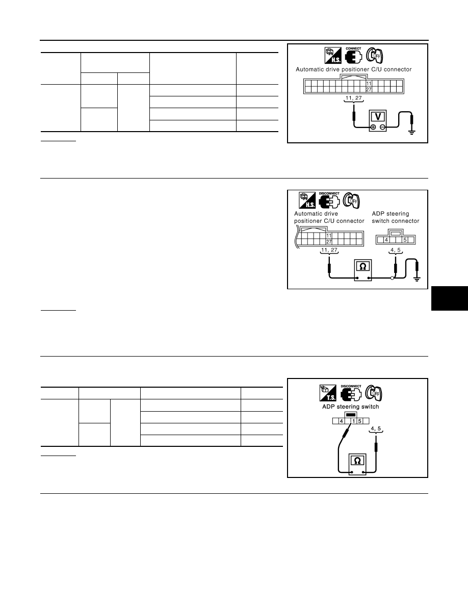
Telescopic switch operate, check voltage between automatic drive positioner control unit connector and
ground.
Connector
Terminal
Rear lifting switch condition
Continuity
B175
27
61B
UP
Yes
Other than above
No
40
DOWN
Yes
Other than above
No
PIIB8596E
61B (B/Y) – Ground
: Continuity should exist.
PIIB8597E
Monitor item
[OPERATION or UNIT]
Contents
TELESCO SW-FR
“ON/OFF”
(ON/OFF) status judged from the telescoping
switch (FR) signal is displayed.
TELESCO SW-RR
“ON/OFF”
(ON/OFF) status judged from the telescoping
switch (RR) signal is displayed.
AUTOMATIC DRIVE POSITIONER
SE-69
< SERVICE INFORMATION >
C
D
E
F
G
H
J
K
L
M
A
B
SE
N
O
P
OK or NG
OK
>> Telescopic switch circuit is OK.
NG
>> GO TO 2.
2.
CHECK TELESCOPIC CIRCUIT HARNESS CONTINUITY
1.
Disconnect automatic drive positioner control unit connector and ADP steering switch connector.
2.
Check continuity between automatic drive positioner control unit
connector M49 terminals 11, 27 and ADP steering switch con-
nector M13 terminals 4, 5.
3.
Check continuity between automatic drive positioner control unit
connector M49 terminals 11, 27 and ground.
OK or NG
OK
>> GO TO 3.
NG
>> Repair or replace harness between automatic drive positioner control unit and ADP steering
switch.
3.
CHECK TELESCOPIC SWITCH
ADP steering switch operate, check continuity between ADP steering switch connector M13 terminal 4, 5 and
1.
OK or NG
OK
>> GO TO 4.
NG
>> Replace ADP steering switch.
4.
CHECK ADP STEERING SWITCH GROUND CIRCUIT
Connector
Terminals
(Wire color)
Telescopic switch condition
Voltage (V)
(Approx.)
(+)
(–)
M49
11 (BR)
Ground
FORWARD
0
Other than above
5
27 (LG)
BACKWARD
0
Other than above
5
PIIA5073E
11 (BR) – 5 (BR)
: Continuity should exist.
27 (LG) – 4 (LG)
: Continuity should exist.
11 (BR) – Ground
: Continuity should not exist.
27 (LG) – Ground
: Continuity should not exist.
PIIA5071E
Connector
Terminal
ADP steering switch condition
Continuity
M13
5
1
FORWARD
Yes
Other than above
No
4
BACKWARD
Yes
Other than above
No
PIIA4481E
Нет комментариевНе стесняйтесь поделиться с нами вашим ценным мнением.
Текст