Infiniti FX35 / FX45. Manual — part 495

DTC P0031, P0032, P0051, P0052 A/F SENSOR 1 HEATER
EC-741
< SERVICE INFORMATION >
[VK45DE]
C
D
E
F
G
H
I
J
K
L
M
A
EC
N
P
O
Do not use ECM ground terminals when measuring input/output voltage. Doing so may result in dam-
age to the ECM's transistor. Use a ground other than ECM terminals, such as the ground.
: Average voltage for pulse signal (Actual pulse signal can be confirmed by oscilloscope.)
TER-
MI-
NAL
NO.
WIRE
COLOR
ITEM
CONDITION
DATA (DC Voltage)
2
P
A/F sensor 1 heater
(Bank 1)
[Engine is running]
• Warm-up condition
• Idle speed
Approximately 5V
16
R
A/F sensor 1 (Bank 1)
[Engine is running]
• Warm-up condition
• Idle speed
Approximately 3.1V
35
G
Approximately 2.6V
56
B
Approximately 2.3V
75
OR
Approximately 2.3V
PBIB1584E

EC-742
< SERVICE INFORMATION >
[VK45DE]
DTC P0031, P0032, P0051, P0052 A/F SENSOR 1 HEATER
BANK 2
Specification data are reference values and are measured between each terminal and ground.
Pulse signal is measured by CONSULT-III.
CAUTION:
Do not use ECM ground terminals when measuring input/output voltage. Doing so may result in dam-
age to the ECM's transistor. Use a ground other than ECM terminals, such as the ground.
TBWM1372E

DTC P0031, P0032, P0051, P0052 A/F SENSOR 1 HEATER
EC-743
< SERVICE INFORMATION >
[VK45DE]
C
D
E
F
G
H
I
J
K
L
M
A
EC
N
P
O
: Average voltage for pulse signal (Actual pulse signal can be confirmed by oscilloscope.)
Diagnosis Procedure
INFOID:0000000001326567
1.
CHECK GROUND CONNECTIONS
1.
Turn ignition switch OFF.
2.
Loosen and retighten three ground screws on the body.
Refer to
OK or NG
OK
>> GO TO 2.
NG
>> Repair or replace ground connections.
2.
CHECK AIR FUEL RATIO (A/F) SENSOR 1 POWER SUPPLY CIRCUIT
1.
Disconnect air fuel ratio (A/F) sensor 1 harness connector.
2.
Turn ignition switch ON.
TER-
MI-
NAL
NO.
WIRE
COLOR
ITEM
CONDITION
DATA (DC Voltage)
24
P
A/F sensor 1 heater
(Bank 2)
[Engine is running]
• Warm-up condition
• Idle speed
Approximately 5V
57
G
A/F sensor 1 (Bank 2)
[Engine is running]
• Warm-up condition
• Idle speed
Approximately 2.6V
58
L
Approximately 2.3V
76
R
Approximately 3.1V
77
OR
Approximately 2.3V
PBIB1584E
PBIB2195E
: Vehicle front
1.
A/F sensor 1 (Bank 2)
harness connector
2.
A/F sensor 1 (Bank 1)
harness connector
PBIB3246E
EC-744
< SERVICE INFORMATION >
[VK45DE]
DTC P0031, P0032, P0051, P0052 A/F SENSOR 1 HEATER
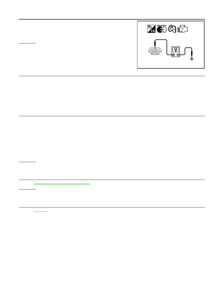
3.
Check voltage between A/F sensor 1 terminal 3 and ground with
CONSULT-III or tester.
OK or NG
OK
>> GO TO 4.
NG
>> GO TO 3.
3.
DETECT MALFUNCTIONING PART
Check the following.
• Harness connectors E19, F49
• IPDM E/R connector E7
• 10A fuse
• Harness for open or short between A/F sensor 1 and fuse
>> Repair or replace harness or connectors.
4.
CHECK A/F SENSOR 1 HEATER OUTPUT SIGNAL CIRCUIT
1.
Turn ignition switch OFF.
2.
Disconnect ECM harness connector.
3.
Check harness continuity between the following;
ECM terminal 2 and A/F sensor 1 (Bank 1) terminal 4 or
ECM terminal 24 and A/F sensor 1 (Bank 2) terminal 4.
Refer to Wiring Diagram.
4.
Also check harness for short to ground and short to power.
OK or NG
OK
>> GO TO 5.
NG
>> Repair open circuit or short to ground or short to power in harness or connectors.
5.
CHECK A/F SENSOR 1 HEATER
EC-744, "Component Inspection"
OK or NG
OK
>> GO TO 6.
NG
>> Replace malfunctioning air fuel ratio sensor 1.
6.
CHECK INTERMITTENT INCIDENT
>> INSPECTION END
Component Inspection
INFOID:0000000001326568
AIR FUEL RATIO (A/F) SENSOR 1 HEATER
Voltage: Battery voltage
PBIB1683E
Continuity should exist.
Нет комментариевНе стесняйтесь поделиться с нами вашим ценным мнением.
Текст