Infiniti FX35 / FX45. Manual — part 494
DTC P0011, P0021 IVT CONTROL
EC-737
< SERVICE INFORMATION >
[VK45DE]
C
D
E
F
G
H
I
J
K
L
M
A
EC
N
P
O
>> INSPECTION END
Component Inspection
INFOID:0000000001326560
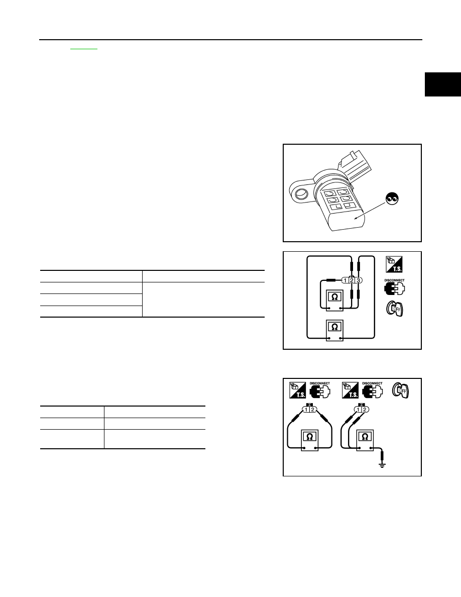
INTAKE VALVE TIMING CONTROL POSITION SENSOR
1.
Disconnect intake valve timing control position sensor harness connector.
2.
Loosen the fixing bolt of the sensor.
3.
Remove the sensor.
4.
Visually check the sensor for chipping.
5.
Check resistance as shown below.
6.
If NG, replace intake valve timing control position sensor.
INTAKE VALVE TIMING CONTROL SOLENOID VALVE
1.
Disconnect intake valve timing control solenoid valve harness connector.
2.
Check resistance between intake valve timing control solenoid
valve terminals as follows.
If NG, replace intake valve timing control solenoid valve.
If OK, go to next step.
3.
Remove intake valve timing control solenoid valve.
SEF362Z
Terminal No. (Polarity)
Resistance
Ω
[at 25
°
C (77
°
F)]
3 (+) - 1 (-)
Except 0 or
∞
2 (+) - 1 (-)
3 (+) - 2 (-)
PBIB0194E
Terminals
Resistance
1 and 2
7.0 - 7.5
Ω
[at 20
°
C (68
°
F)]
1 or 2 and ground
∞Ω
(Continuity should not exist)
PBIB0193E
EC-738
< SERVICE INFORMATION >
[VK45DE]
DTC P0011, P0021 IVT CONTROL
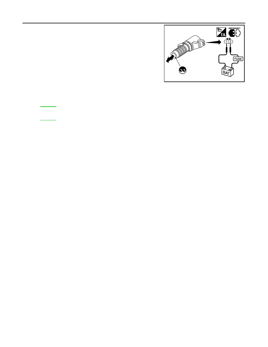
4.
Provide 12V DC between intake valve timing control solenoid
valve terminals and then interrupt it. Make sure that the plunger
moves as shown in the figure.
CAUTION:
Do not apply 12V DC continuously for 5 seconds or more.
Doing so may result in damage to the coil in intake valve
timing control solenoid valve.
If NG, replace intake valve timing control solenoid valve.
NOTE:
Always replace O-ring when intake valve timing control
solenoid valve is removed.
Removal and Installation
INFOID:0000000001326561
INTAKE VALVE TIMING CONTROL POSITION SENSOR
.
INTAKE VALVE TIMING CONTROL SOLENOID VALVE
.
PBIB2275E

DTC P0031, P0032, P0051, P0052 A/F SENSOR 1 HEATER
EC-739
< SERVICE INFORMATION >
[VK45DE]
C
D
E
F
G
H
I
J
K
L
M
A
EC
N
P
O
DTC P0031, P0032, P0051, P0052 A/F SENSOR 1 HEATER
Description
INFOID:0000000001326562
SYSTEM DESCRIPTION
The ECM performs ON/OFF duty control of the A/F sensor 1 heater corresponding to the engine operating
condition to keep the temperature of A/F sensor 1 element at the specified range.
CONSULT-III Reference Value in Data Monitor Mode
INFOID:0000000001326563
Specification data are reference values.
On Board Diagnosis Logic
INFOID:0000000001326564
DTC Confirmation Procedure
INFOID:0000000001326565
NOTE:
If DTC Confirmation Procedure has been previously conducted, always turn ignition switch OFF and wait at
least 10 seconds before conducting the next test.
TESTING CONDITION:
Before performing the following procedure, confirm that battery voltage is between 10.5V and 16V at
idle.
1.
Start engine and let it idle for at least 10 seconds.
2.
Check 1st trip DTC.
3.
If 1st trip DTC is detected, go to
Sensor
Input Signal to ECM
ECM function
Actuator
Camshaft position sensor (PHASE)
Crankshaft position sensor (POS)
Engine speed
Air fuel ratio (A/F) sensor 1
heater control
Air fuel ratio (A/F) sensor 1
heater
Mass air flow sensor
Amount of intake air
MONITOR ITEM
CONDITION
SPECIFICATION
A/F S1 HTR (B1)
A/F S1 HTR (B2)
• Engine: After warming up, idle the engine
0 - 100%
DTC No.
Trouble diagnosis name
DTC detecting condition
Possible cause
P0031
0031
(Bank 1)
Air fuel ratio (A/F) sensor
1 heater control circuit low
The current amperage in the A/F sensor 1 heater
circuit is out of the normal range.
(An excessively low voltage signal is sent to ECM
through the A/F sensor 1 heater.)
• Harness or connectors
(The A/F sensor 1 heater circuit is
open or shorted.)
• A/F sensor 1 heater
P0051
0051
(Bank 2)
P0032
0032
(Bank 1)
Air fuel ratio (A/F) sensor
1 heater control circuit
high
The current amperage in the A/F sensor 1 heater
circuit is out of the normal range.
(An excessively high voltage signal is sent to ECM
through the A/F sensor 1 heater.)
• Harness or connectors
(The A/F sensor 1 heater circuit is
shorted.)
• A/F sensor 1 heater
P0052
0052
(Bank 2)
EC-740
< SERVICE INFORMATION >
[VK45DE]
DTC P0031, P0032, P0051, P0052 A/F SENSOR 1 HEATER
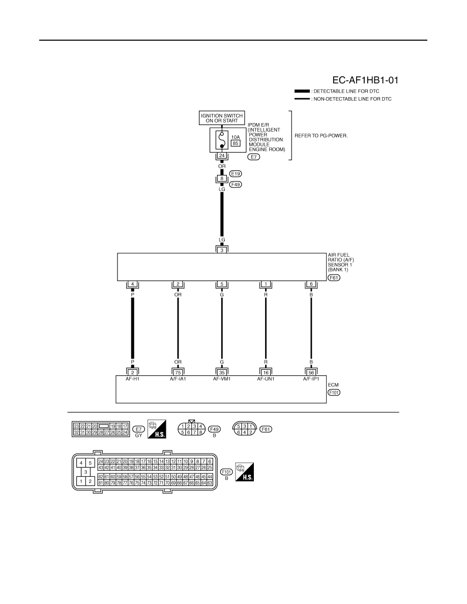
Wiring Diagram
INFOID:0000000001326566
BANK 1
Specification data are reference values and are measured between each terminal and ground.
Pulse signal is measured by CONSULT-III.
CAUTION:
TBWM1371E
Нет комментариевНе стесняйтесь поделиться с нами вашим ценным мнением.
Текст