Infiniti FX35 / FX45. Manual — part 907
SC-16
< SERVICE INFORMATION >
STARTING SYSTEM
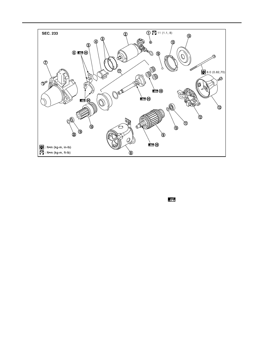
VQ35DE ENGINE MODELS (2WD) (S114-880A)
1.
Nut
2.
Magnetic switch assembly
3.
Adjusting plate
4.
Packing
5.
Plate
6.
Shift lever
7.
Front bracket assembly
8.
Yoke assembly
9.
Armature assembly
10. Washer
11.
Rear bearing
12. Brush holder assembly
13. Rear bracket assembly
14. Cover
15. Packing
16. Ball
17. Shaft gear assembly
18. Clutch gear assembly
19. Pinion stopper
20. Stopper clip
(H): High-temperature grease point
PKID0693E
STARTING SYSTEM
SC-17
< SERVICE INFORMATION >
C
D
E
F
G
H
I
J
L
M
A
B
SC
N
O
P
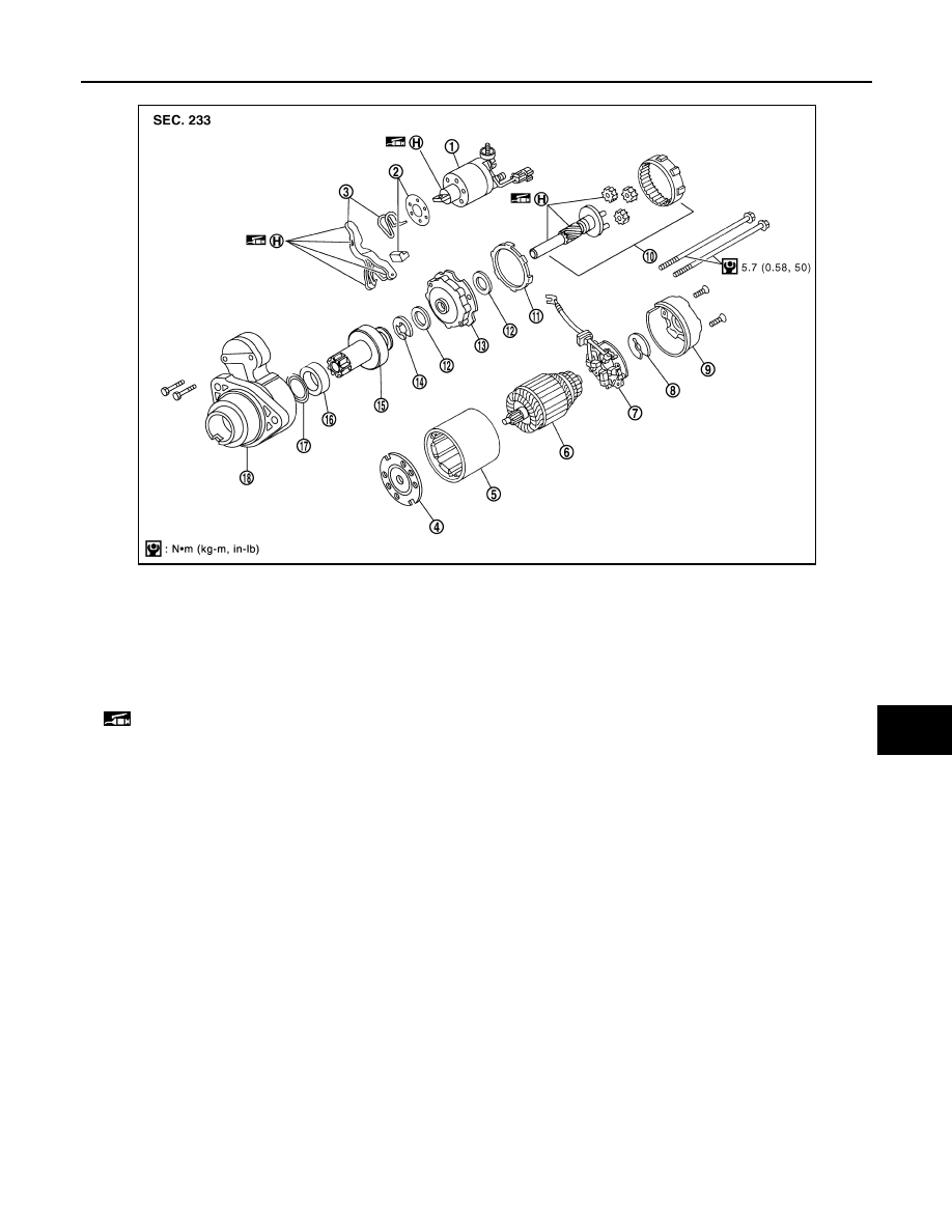
VQ35DE ENGINE MODELS (AWD) (S114-881A)
1.
Magnetic switch assembly
2.
Dust cover kit
3.
Shift lever set
4.
Center bracket (A)
5.
Yoke assembly
6.
Armature assembly
7.
Brush holder assembly
8.
Thrust washer
9.
Rear cover assembly
10. Shaft gear assembly
11.
Packing
12. Thrust washer
13. Center bracket (P)
14.
E-ring
15. Pinion assembly
16. Ball bearing
17.
Caul
18. Gear case assembly
(H): High-temperature grease point
PKID0694E
SC-18
< SERVICE INFORMATION >
STARTING SYSTEM
Inspection After Disassembly
INFOID:0000000001328253
PINION/CLUTCH CHECK
1.
Inspect pinion teeth.
• Replace pinion if teeth are worn or damaged. (Also check condition of ring gear teeth.)
2.
Inspect reduction gear teeth.
• Replace reduction gear if teeth are worn or damaged. (Also check condition of armature shaft gear
teeth.)
3.
Check to see if pinion locks in one direction and rotates smoothly in the opposite direction.
• If it locks or rotates in both directions, or unusual resistance is evident, replace.
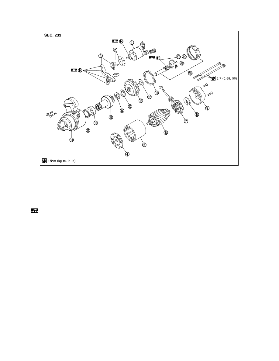
1.
Magnetic switch assembly
2.
Dust cover kit
3.
Shift lever set
4.
Center bracket (A)
5.
Yoke assembly
6.
Armature assembly
7.
Brush holder assembly
8.
Thrust washer
9.
Rear cover assembly
10. Shaft gear assembly
11.
Packing
12. Thrust washer
13. Center bracket (P)
14.
E-ring
15. Pinion assembly
16. Ball bearing
17.
Caul
18. Gear case assembly
(H): High-temperature grease point
PKID0695E
CHARGING SYSTEM
SC-19
< SERVICE INFORMATION >
C
D
E
F
G
H
I
J
L
M
A
B
SC
N
O
P
CHARGING SYSTEM
System Description
INFOID:0000000001328254
The alternator provides DC voltage to operate the vehicle's electrical system and to keep the battery charged.
The voltage output is controlled by the IC regulator.
Power is supplied at all times
• through 10A fuse (No. 33, located in the fuse and fusible link block)
• to alternator terminal 4 (“S” terminal).
“B” Terminal supplies power to charge the battery and operate the vehicle's electrical system. Output voltage
is controlled by the IC regulator at terminal 4 (“S” terminal) detecting the input voltage.
The charging circuit is protected by the 120A fusible link (VK45DE and VQ35DE AWD).
The alternator is grounded to the engine block.
With the ignition switch in the ON or START position, power is supplied
• through 10A fuse [No. 14, located in the fuse block (J/B)]
• to combination meter terminal 7 for the charge warning lamp.
Ground is supplied
• to combination meter terminal 2
• through alternator terminal 3 (“L” terminal)
• to alternator terminal 2 (“E” terminal) (VK45DE) or through case ground (VQ35DE)
• through ground E304 (VK45DE).
With power and ground supplied, the charge warning lamp will illuminate. When the alternator is providing suf-
ficient voltage with the engine running, the ground is opened and the charge warning lamp will go off.
If the charge warning lamp illuminates with the engine running, a malfunction is indicated.
MALFUNCTION INDICATOR
The IC regulator warning function activates to illuminate charge warning lamp, if any of the following symp-
toms occur while alternator is operating:
• Excessive voltage is produced.
• No voltage is produced.
Нет комментариевНе стесняйтесь поделиться с нами вашим ценным мнением.
Текст