Infiniti FX35 / FX45. Manual — part 786
DAYTIME LIGHT SYSTEM
LT-39
< SERVICE INFORMATION >
C
D
E
F
G
H
I
J
L
M
A
B
LT
N
O
P
Termi-
nal No.
Wire
color
Signal name
Measuring condition
Reference value
Ignition
switch
Operation or condition
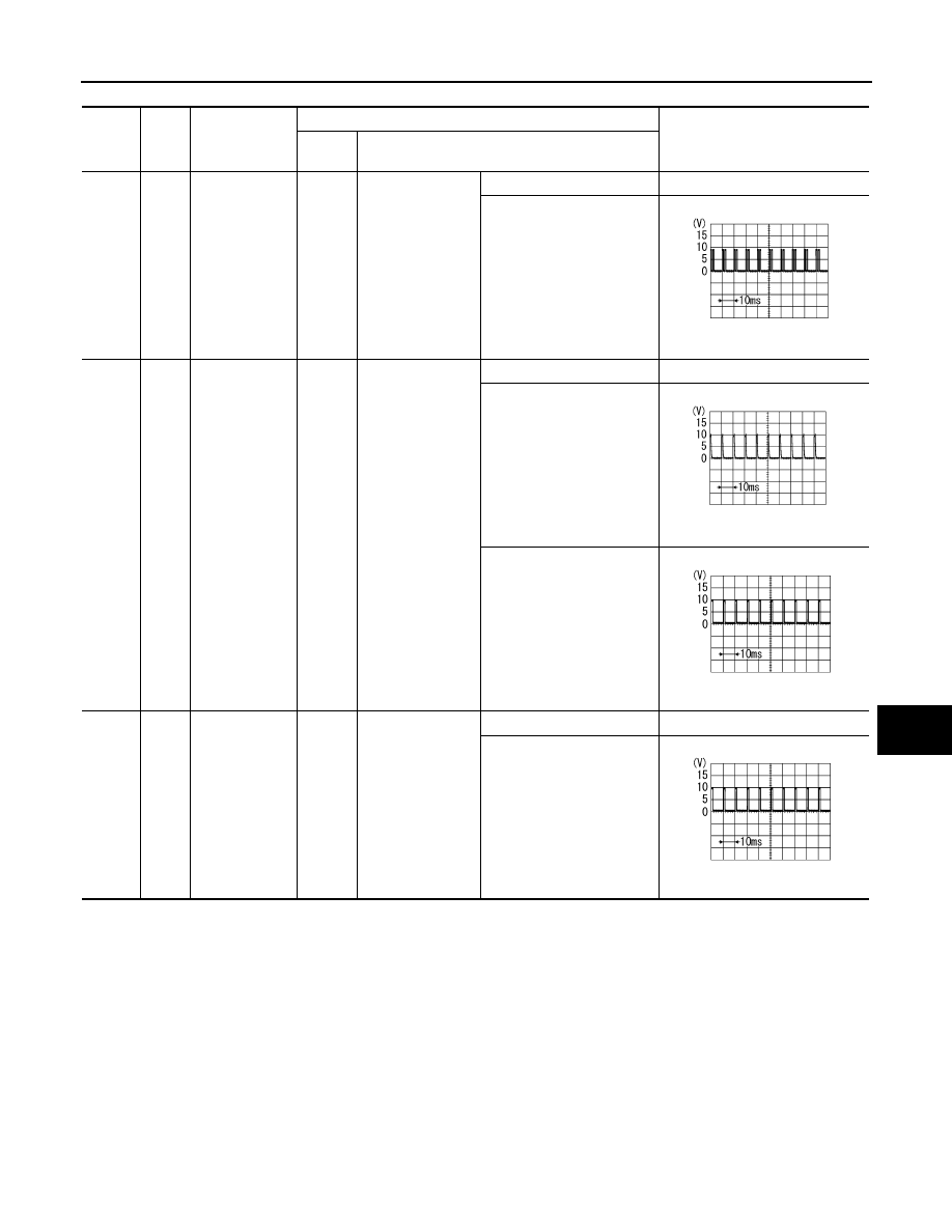
2
GY
Combination
switch input 5
ON
Lighting, turn, wip-
er switch
(Wiper intermittent
dial position 4)
OFF
Approx. 0 V
Lighting switch 2ND
Approx. 2.0 V
3
L/B
Combination
switch input 4
ON
Lighting, turn, wip-
er switch
(Wiper intermittent
dial position 4)
OFF
Approx. 0 V
Front fog lamp switch
(Operate only front fog lamp
switch)
Approx. 0.8 V
Any of the conditions below
• Lighting switch 2ND
• Lighting switch PASSING
(Operates only PASSING
switch)
Approx. 1.0 V
4
PU/W
Combination
switch input 3
ON
Lighting, turn, wip-
er switch
(Wiper intermittent
dial position 4)
OFF
Approx. 0 V
Any of the conditions below
• Lighting switch AUTO
Approx. 1.0 V
PKIB4953J
PKIB4955J
PKIB4959J
PKIB4959J
LT-40
< SERVICE INFORMATION >
DAYTIME LIGHT SYSTEM
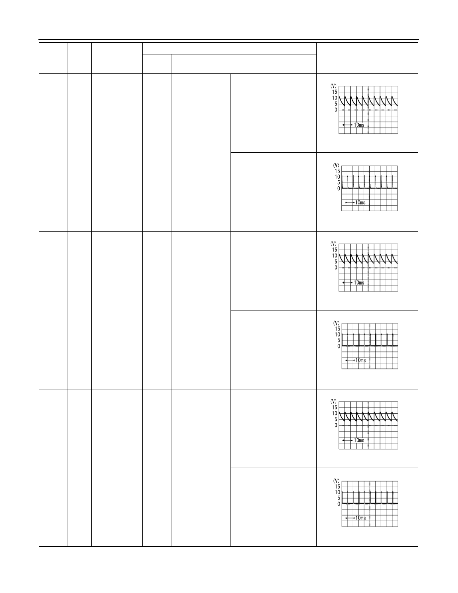
32
GY/R
Combination
switch output 5
ON
Lighting, turn, wip-
er switch (Wiper
intermittent dial
position 4)
OFF
Approx. 7.2 V
Front fog lamp switch
(Operates only front fog
lamp switch)
Approx. 1.0 V
33
G
Combination
switch output 4
ON
Lighting, turn, wip-
er switch (Wiper
intermittent dial
position 4)
OFF
Approx. 7.2 V
Lighting switch AUTO
Approx. 1.2 V
34
W/B
Combination
switch output 3
ON
Lighting, turn, wip-
er switch (Wiper
intermittent dial
position 4)
OFF
Approx. 7.2 V
Lighting switch 2ND
Approx. 1.2 V
Termi-
nal No.
Wire
color
Signal name
Measuring condition
Reference value
Ignition
switch
Operation or condition
PKIB4960J
PKIB4956J
PKIB4960J
PKIB4958J
PKIB4960J
PKIB4958J

DAYTIME LIGHT SYSTEM
LT-41
< SERVICE INFORMATION >
C
D
E
F
G
H
I
J
L
M
A
B
LT
N
O
P
How to Proceed with Trouble Diagnosis
INFOID:0000000001328298
1.
Confirm the symptom or customer complaint.
2.
Understand operation description and function description. Refer to
.
3.
Perform Preliminary Check. Refer to
4.
Check symptom and repair or replace the cause of malfunction.
5.
Does daytime light lamp operate normally? If YES, GO TO 6. If NO, GO TO 4.
6.
INSPECTION END
Preliminary Check
INFOID:0000000001328299
CHECK POWER SUPPLY AND GROUND CIRCUIT
1.
CHECK FUSES
Check for blown fuses.
LT-35, "Wiring Diagram - DTRL -"
OK or NG
35
W/G
Combination
switch output 2
ON
Lighting, turn, wip-
er switch
(Wiper intermittent
dial position 4)
OFF
Approx. 7.2 V
Any of the conditions below
• Lighting switch 2ND
• Lighting switch PASSING
(Operates only PASSING
switch)
Approx. 1.2 V
38
W/L
Ignition switch
(ON)
ON
—
Battery voltage
39
L
CAN
−
H
—
—
—
40
P
CAN
−
L
—
—
—
42
L/R
Battery power
supply
OFF
—
Battery voltage
49
B
Ground
ON
—
Approx. 0 V
52
B
Ground
ON
—
Approx. 0 V
55
G
Battery power
supply
OFF
—
Battery voltage
Termi-
nal No.
Wire
color
Signal name
Measuring condition
Reference value
Ignition
switch
Operation or condition
PKIB4960J
PKIB4958J
Unit
Power source
Fuse and fusible link No.
BCM
Battery
M
22
Ignition switch ON or START position
1
Daytime light relay
Battery
36

LT-42
< SERVICE INFORMATION >
DAYTIME LIGHT SYSTEM
OK
>> GO TO 2.
NG
>> If fuse is blown, be sure to eliminate cause of malfunction before installing new fuse. Refer to
2.
CHECK POWER SUPPLY CIRCUIT
1.
Turn ignition switch OFF.
2.
Disconnect BCM connector.
3.
Check voltage between BCM harness connector and ground.
OK or NG
OK
>> GO TO 3.
NG
>> Repair harness or connector.
3.
CHECK GROUND CIRCUIT
Check continuity between BCM harness connector and ground.
OK or NG
OK
>> INSPECTION END
NG
>> Repair harness or connector.
INSPECTION PARKING BRAKE SWITCH CIRCUIT
1.
CHECK BRAKE INDICATOR
1.
Turn ignition switch ON.
2.
When a parking brake is made ON/OFF, it checks whether brake indicator lamp of combination meter
lights up / puts out the light.
OK or NG
OK
>> INSPECTION END
NG
>> GO TO 2.
2.
CHECK PARKING BRAKE SWITCH SIGNAL
1.
Turn ignition switch OFF.
2.
Disconnect parking brake switch connector.
3.
Turn ignition switch ON.
4.
Check voltage between parking brake switch harness connector
E207 terminal 1 and ground.
OK or NG
OK
>> Replace parking brake switch.
NG
>> GO TO 3.
3.
CHECK PARKING BRAKE SWITCH CIRCUIT
(+)
(-)
Ignition switch position
BCM con-
nector
Terminal
OFF
ON
M3
38
Ground
Approx. 0 V
Battery voltage
M4
42
Battery voltage
Battery voltage
55
Battery voltage
Battery voltage
PKIA7520E
BCM connector
Terminal
Ground
Continuity
M4
49
Yes
52
SKIA5294E
1 – Ground
: Battery voltage.
SKIA5876E
Нет комментариевНе стесняйтесь поделиться с нами вашим ценным мнением.
Текст