Infiniti FX35 / FX45. Manual — part 39
AT-84
< SERVICE INFORMATION >
TROUBLE DIAGNOSIS
Data are reference value and are measured between each terminal and ground.
CONSULT-III Function (TRANSMISSION)
INFOID:0000000001327163
CONSULT-III can display each diagnostic item using the diagnostic test models shown following.
FUNCTION
CONSULT-III REFERENCE VALUE
NOTICE:
1.
The CONSULT-III electrically displays shift timing and lock-up timing (that is, operation timing of each
solenoid).
Check for time difference between actual shift timing and the CONSULT-III display. If the difference is
noticeable, mechanical parts (except solenoids, sensors, etc.) may be malfunctioning. Check mechanical
parts using applicable diagnostic procedures.
2.
Shift schedule (which implies gear position) displayed on CONSULT-III and that indicated in Service Man-
ual may differ slightly. This occurs because of the following reasons:
-
Actual shift schedule has more or less tolerance or allowance,
-
Shift schedule indicated in Service Manual refers to the point where shifts start, and
-
Gear position displayed on CONSULT-III indicates the point where shifts are completed.
Terminal
Wire
color
Item
Condition
Data (Approx.)
1
LG
Power supply
(Memory back-up)
Always
Battery voltage
2
LG
Power supply
(Memory back-up)
Always
Battery voltage
3
L
CAN-H
–
–
4
PU
K-line (CONSULT-
III signal)
The terminal is connected to the data link connector for CONSULT-III.
–
5
B
Ground
–
–
6
Y
Power supply
–
Battery voltage
–
0 V
7
OR
Back-up lamp re-
lay
Selector lever in “R” position.
0 V
Selector lever in other positions.
Battery voltage
8
P
CAN-L
–
–
9
GY
Starter relay
Selector lever in “N” and “P” positions.
Battery voltage
Selector lever in other positions.
0 V
10
B
Ground
–
–
Diagnostic test mode
Function
Work support
This mode enables a technician to adjust some devices faster and more accurately by following the in-
dications on CONSULT-III.
Self-diagnostic results
Self-diagnostic results can be read and erased quickly.
Data monitor
Input/Output data in the ECU can be read.
CAN diagnostic support mon-
itor
The results of transmit/receive diagnosis of CAN communication can be read.
Function test
Performed by CONSULT-III instead of a technician to determine whether each system is “OK” or “NG”.
DTC work support
Select the operating condition to confirm Diagnosis Trouble Codes.
ECU part number
TCM part number can be read.
TROUBLE DIAGNOSIS
AT-85
< SERVICE INFORMATION >
D
E
F
G
H
I
J
K
L
M
A
B
AT
N
O
P
3.
Display of solenoid valves on CONSULT-III changes at the start of shifting, while gear position is displayed
upon completion of shifting (which is computed by TCM).
Item name
Condition
Display value (Approx.)
ATF TEMP SE 1
0
°
C (32
°
F)
−
20
°
C (68
°
F)
−
80
°
C (176
°
F)
3.3
−
2.7
−
0.9 V
ATF TEMP SE 2
3.3
−
2.5
−
0.7 V
ATF TEMP 1
Ignition switch ON
Measured ATF temperature is dis-
played.
TCC SOLENOID
Lock-up is active
0.4
−
0.6 A
SLCT LVR POSI
Selector lever in “N” and “P” positions.
N/P
Selector lever in “R” position.
R
Selector lever in “D” position.
D
VHCL/S SE-A/T
During driving
Approximately matches the speedom-
eter reading.
VEHICLE SPEED
During driving
Approximately matches the speedom-
eter reading.
ENGINE SPEED
Engine running
Closely matches the tachometer read-
ing.
LINE PRES SOL
During driving
0.2
−
0.6 A
TURBINE REV
During driving (lock-up ON)
Approximately matches the engine
speed.
VHCL/S SE-MTR
During driving
Approximately matches the speedom-
eter reading.
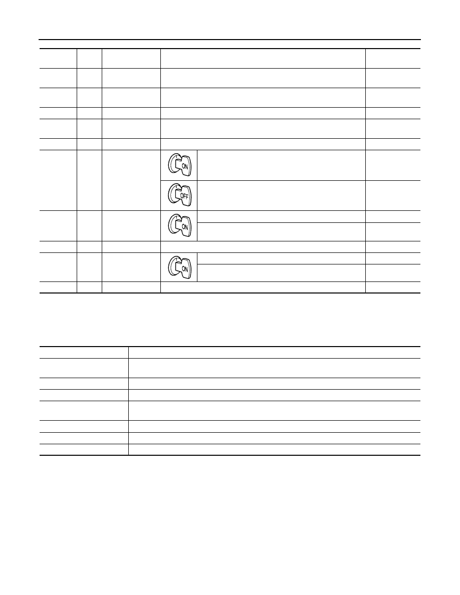
ATF PRES SW 2
Low coast brake engaged. Refer to
ON
Low coast brake disengaged. Refer to
. OFF
I/C SOLENOID
Input clutch disengaged. Refer to
.
0.6
−
0.8 A
Input clutch engaged. Refer to
.
0
−
0.05 A
FR/B SOLENOID
.
0.6
−
0.8 A
Front brake disengaged. Refer to
. 0
−
0.05 A
D/C SOLENOID
Direct clutch disengaged. Refer to
.
0.6
−
0.8 A
Direct clutch engaged. Refer to
.
0
−
0.05 A
HLR/C SOL
High and low reverse clutch disengaged. Refer to
.
0.6
−
0.8 A
High and low reverse clutch engaged. Refer to
.
0
−
0.05 A
ON OFF SOL
Low coast brake engaged. Refer to
ON
Low coast brake disengaged. Refer to
OFF
MANU MODE SW
Manual shift gate position (neutral)
ON
Other than the above
OFF
NON M-MODE SW
Manual shift gate position
OFF
Other than the above
ON
UP SW LEVER
Selector lever: + side
ON
Other than the above
OFF
DOWN SW LEVER
Selector lever: - side
ON
Other than the above
OFF
STARTER RELAY
Selector lever in “N” and “P” positions.
ON
Selector lever in other positions.
OFF
ACCELE POSI
Released accelerator pedal.
0.0/8
Fully depressed accelerator pedal.
8.0/8

AT-86
< SERVICE INFORMATION >
TROUBLE DIAGNOSIS
SELF-DIAGNOSTIC RESULT MODE
After performing “SELF-DIAGNOSTIC RESULT MODE”, place check marks for results on the
Perform Trouble Diagnosis for Quick and Accurate Repair"
. Reference pages are provided following the items.
Display Items List
X: Applicable, —: Not applicable
CLSD THL POS
Released accelerator pedal.
ON
Fully depressed accelerator pedal.
OFF
W/O THL POS
Fully depressed accelerator pedal.
ON
Released accelerator pedal.
OFF
BRAKE SW
Depressed brake pedal.
ON.
Released brake pedal.
OFF
GEAR
During driving.
1,2,3,4,5,
Item name
Condition
Display value (Approx.)
Items (CONSULT-
III screen terms)
Malfunction is detected when...
TCM self-di-
agnosis
OBD-II
(DTC)
Reference
page
“TRANS-
MISSION”
with CON-
SULT-III
MIL indica-
tor lamp
(*1)
,
“ENGINE”
with CON-
SULT-III or
GST
CAN COMM CIR-
CUIT
When TCM is not transmitting or receiving CAN communication sig-
nal for 2 seconds or more.
U1000
U1000
STARTER RELAY/
CIRC
If this signal is ON other than in “P” or “N” position, this is judged to
be a malfunction.
(And if it is OFF in “P” or “N” position, this too is judged to be a mal-
function.)
P0615
—
TCM
TCM is malfunctioning.
P0700
P0700
PNP SW/CIRC
• PNP switch 1-4 signals input with impossible pattern.
• “P” position is detected from “N” position without any other posi-
tion being detected in between.
P0705
P0705
TURBINE REV S/
CIRC
• TCM does not receive the proper voltage signal from the sensor.
• TCM detects an irregularity only at position of 4th gear for turbine
revolution sensor 2.
P0717
P0717
VEH SPD SEN/CIR
AT
• Signal from vehicle speed sensor A/T (Revolution sensor) not in-
put due to cut line or the like.
• Unexpected signal input during running.
• After ignition switch is turned ON, unexpected signal input from
vehicle speed sensor MTR before the vehicle starts moving.
P0720
P0720
ENGINE SPEED
SIG
TCM does not receive the CAN communication signal from the
ECM.
P0725
P0725
A/T 1ST GR
FNCTN
A/T cannot shift to 1st gear.
P0731
P0731
A/T 2ND GR
FNCTN
A/T cannot shift to 2nd gear.
P0732
P0732
A/T 3RD GR
FNCTN
A/T cannot shift to 3rd gear.
P0733
P0733
A/T 4TH GR
FNCTN
A/T cannot shift to 4th gear.
P0734
P0734
A/T 5TH GR
FNCTN
A/T cannot shift to 5th gear.
P0735
P0735
TCC SOLENOID/
CIRC
Normal voltage not applied to solenoid due to cut line, short, or the
like.
P0740
P0740

TROUBLE DIAGNOSIS
AT-87
< SERVICE INFORMATION >
D
E
F
G
H
I
J
K
L
M
A
B
AT
N
O
P
EC-71, "Malfunction Indicator Lamp (MIL)"
EC-649, "Malfunction Indicator Lamp (MIL)"
(for VK45DE
engine.)
A/T TCC S/V
FNCTN
• A/T cannot perform lock-up even if electrical circuit is good.
• TCM detects as irregular by comparing difference value with slip
rotation.
P0744
P0744
(*2)
L/PRESS SOL/
CIRC
• Normal voltage not applied to solenoid due to cut line, short, or the
like.
• TCM detects as irregular by comparing target value with monitor
value.
P0745
P0745
TP SEN/CIRC A/T
TCM does not receive the proper accelerator pedal position signals
(input by CAN communication) from ECM.
P1705
P1705
ATF TEMP SEN/
CIRC
During running, the A/T fluid temperature sensor signal voltage is
excessively high or low.
P1710
P0710
VEH SPD SE/CIR-
MTR
• Signal (CAN communication) from vehicle speed sensor MTR not
input due to cut line or the like.
• Unexpected signal input during running.
P1721
—
A/T INTERLOCK
Except during shift change, the gear position and ATF pressure
switch states are monitored and comparative judgement made.
P1730
P1730
A/T 1ST E/BRAK-
ING
Each ATF pressure switch and solenoid current is monitored and if
a pattern is detected having engine braking 1st gear other than in the
M1 position, a malfunction is detected.
P1731
—
I/C SOLENOID/
CIRC
• Normal voltage not applied to solenoid due to functional malfunc-
tion, cut line, short, or the like.
• TCM detects as irregular by comparing target value with monitor
value.
P1752
P1752
FR/B SOLENOID/
CIRC
• Normal voltage not applied to solenoid due to functional malfunc-
tion, cut line, short, or the like.
• TCM detects as irregular by comparing target value with monitor
value.
P1757
P1757
D/C SOLENOID/
CIRC
• Normal voltage not applied to solenoid due to cut line, short, or the
like.
• TCM detects as irregular by comparing target value with monitor
value.
P1762
P1762
HLR/C SOL/CIRC
• Normal voltage not applied to solenoid due to functional malfunc-
tion, cut line, short, or the like.
• TCM detects as irregular by comparing target value with monitor
value.
P1767
P1767
LC/B SOLENOID/
CIRC
Normal voltage not applied to solenoid due to functional malfunction,
cut line, short, or the like.
P1772
P1772
LC/B SOLENOID
FNCT
• TCM detects an improper voltage drop when it tries to operate the
solenoid valve.
• Condition of ATF pressure switch 2 is different from monitor value,
and relation between gear position and actual gear ratio is irregu-
lar.
P1774
P1774
(*2)
MANU MODE SW/
CIRC
When an impossible pattern of switch signals is detected, a malfunc-
tion is detected.
P1815
—
NO DTC IS DE-
TECTED FUR-
THER TESTING
MAY BE RE-
QUIRED
No NG item has been detected.
X
X
—
Items (CONSULT-
III screen terms)
Malfunction is detected when...
TCM self-di-
agnosis
OBD-II
(DTC)
Reference
page
“TRANS-
MISSION”
with CON-
SULT-III
MIL indica-
tor lamp
(*1)
,
“ENGINE”
with CON-
SULT-III or
GST
Нет комментариевНе стесняйтесь поделиться с нами вашим ценным мнением.
Текст