Infiniti FX35 / FX45. Manual — part 359
DTC P0117, P0118 ECT SENSOR
EC-197
< SERVICE INFORMATION >
[VQ35DE]
C
D
E
F
G
H
I
J
K
L
M
A
EC
N
P
O
5.
CHECK INTERMITTENT INCIDENT
>> INSPECTION END
Component Inspection
INFOID:0000000001326018
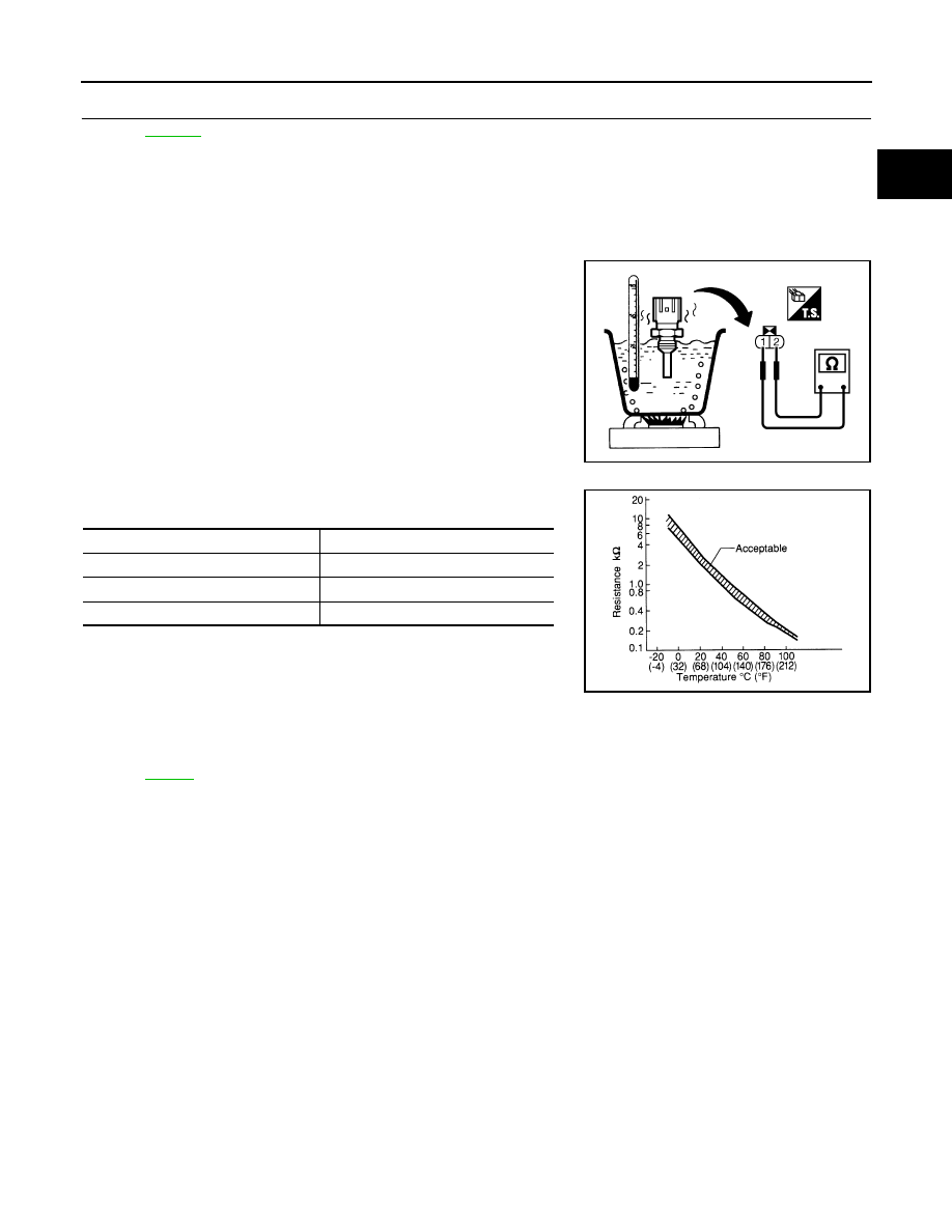
ENGINE COOLANT TEMPERATURE SENSOR
Check resistance between engine coolant temperature sensor termi-
nals 1 and 2 as shown in the figure.
<Reference data>
If NG, replace engine coolant temperature sensor.
Removal and Installation
INFOID:0000000001326019
ENGINE COOLANT TEMPERATURE SENSOR
PBIB2005E
Engine coolant temperature
°
C (
°
F)
Resistance
k
Ω
20 (68)
2.1 - 2.9
50 (122)
0.68 - 1.00
90 (194)
0.236 - 0.260
SEF012P
EC-198
< SERVICE INFORMATION >
[VQ35DE]
DTC P0122, P0123 TP SENSOR
DTC P0122, P0123 TP SENSOR
Component Description
INFOID:0000000001326020
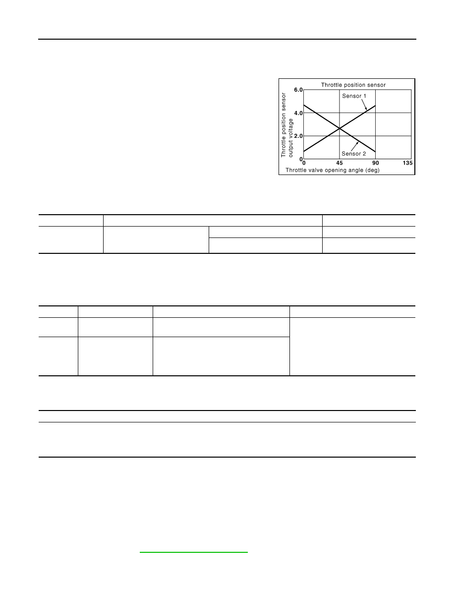
Electric throttle control actuator consists of throttle control motor,
throttle position (TP) sensor, etc. The throttle position sensor
responds to the throttle valve movement.
The throttle position sensor has two sensors. These sensors are a
kind of potentiometers which transform the throttle valve position into
output voltage, and emit the voltage signal to the ECM. In addition,
these sensors detect the opening and closing speed of the throttle
valve and feed the voltage signals to the ECM. The ECM judges the
current opening angle of the throttle valve from these signals and the
ECM controls the throttle control motor to make the throttle valve
opening angle properly in response to driving condition.
CONSULT-III Reference Value in Data Monitor Mode
INFOID:0000000001326021
Specification data are reference values.
*: Throttle position sensor 2 signal is converted by ECM internally. Thus, it differs from ECM terminal voltage signal.
On Board Diagnosis Logic
INFOID:0000000001326022
These self-diagnoses have the one trip detection logic.
FAIL-SAFE MODE
When the malfunction is detected, ECM enters fail-safe mode and the MIL lights up.
DTC Confirmation Procedure
INFOID:0000000001326023
NOTE:
If DTC Confirmation Procedure has been previously conducted, always turn ignition switch OFF and wait at
least 10 seconds before conducting the next test.
TESTING CONDITION:
Before performing the following procedure, confirm that battery voltage is more than 8V at idle.
1.
Start engine and let it idle for 1 second.
2.
Check DTC.
3.
If DTC is detected, go to
.
PBIB0145E
MONITOR ITEM
CONDITION
SPECIFICATION
TP SEN 1-B1
TP SEN 2-B1*
• Ignition switch: ON
(Engine stopped)
• Selector lever: D
Accelerator pedal: Fully released
More than 0.36V
Accelerator pedal: Fully depressed
Less than 4.75V
DTC No.
Trouble diagnosis name
DTC detecting condition
Possible cause
P0122
0122
Throttle position sensor
2 circuit low input
An excessively low voltage from the TP sensor
2 is sent to ECM.
• Harness or connectors
(TP sensor 2 circuit is open or shorted.)
(APP sensor 2 circuit is shorted.)
• Electric throttle control actuator
(TP sensor 2)
• Accelerator pedal position sensor
(APP sensor 2)
P0123
0123
Throttle position sensor
2 circuit high input
An excessively high voltage from the TP sensor
2 is sent to ECM.
Engine operation condition in fail-safe mode
The ECM controls the electric throttle control actuator in regulating the throttle opening in order for the idle position to be within +10
degrees.
The ECM regulates the opening speed of the throttle valve to be slower than the normal condition.
So, the acceleration will be poor.
DTC P0122, P0123 TP SENSOR
EC-199
< SERVICE INFORMATION >
[VQ35DE]
C
D
E
F
G
H
I
J
K
L
M
A
EC
N
P
O
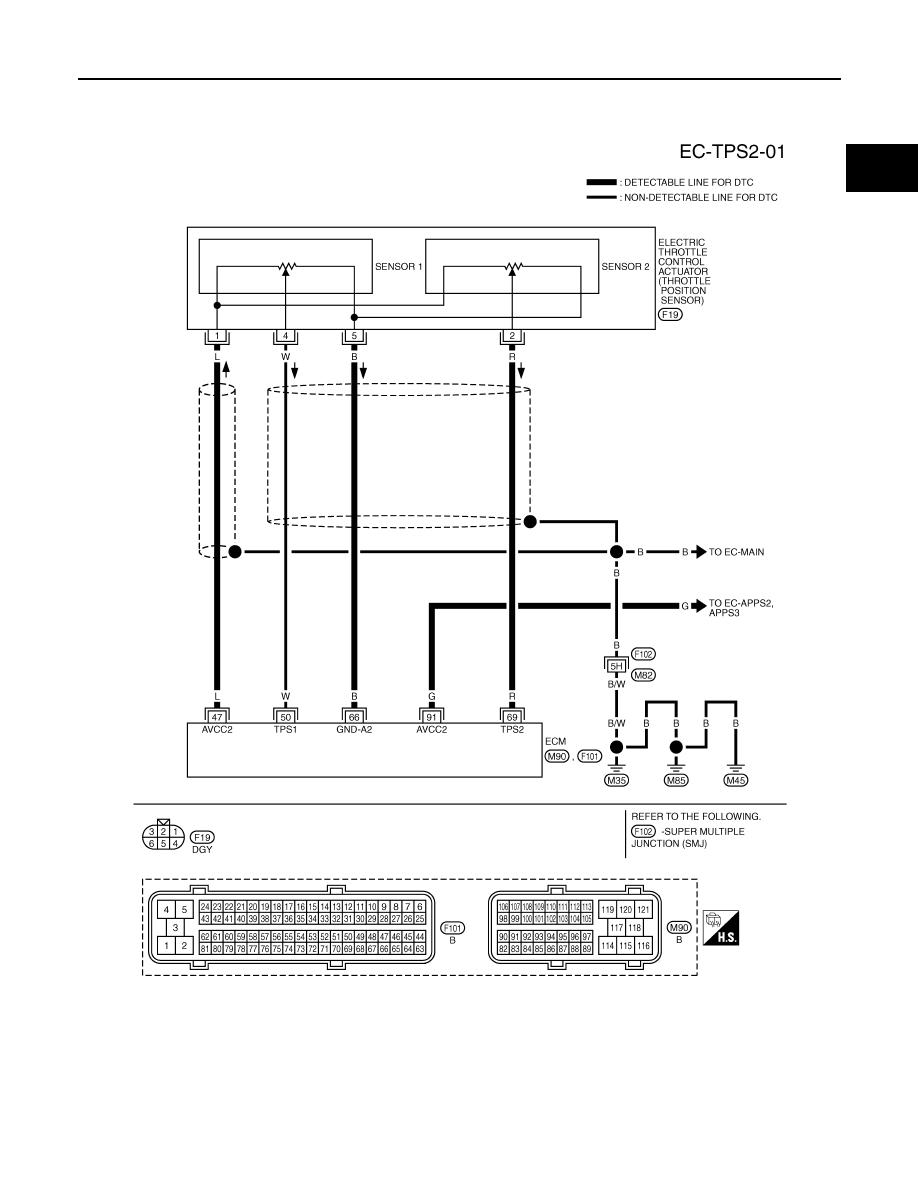
Wiring Diagram
INFOID:0000000001326024
Specification data are reference values and are measured between each terminal and ground.
CAUTION:
Do not use ECM ground terminals when measuring input/output voltage. Doing so may result in dam-
age to the ECM's transistor. Use a ground other than ECM terminals, such as the ground.
TBWM0393E
EC-200
< SERVICE INFORMATION >
[VQ35DE]
DTC P0122, P0123 TP SENSOR
Diagnosis Procedure
INFOID:0000000001326025
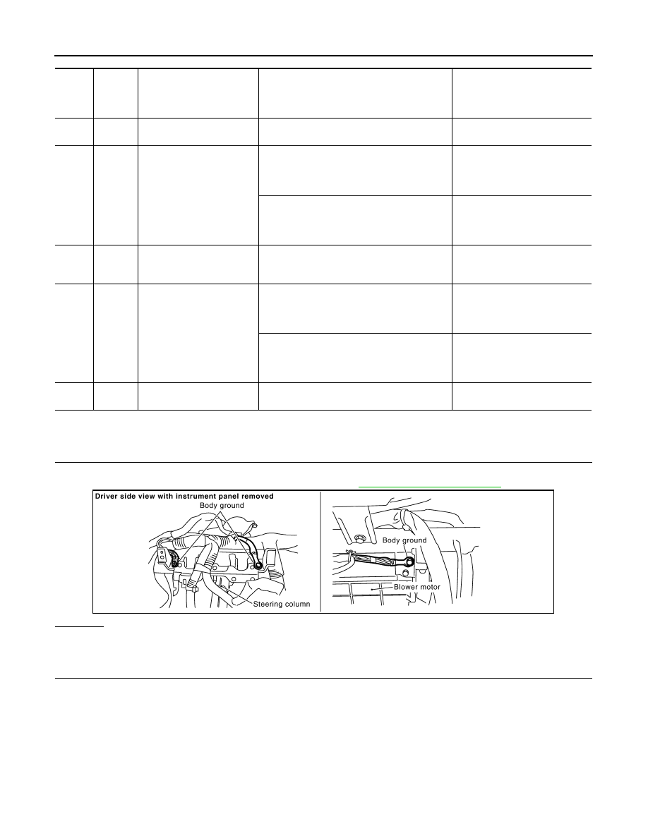
1.
CHECK GROUND CONNECTIONS
1.
Turn ignition switch OFF.
2.
Loosen and retighten ground screw on the body. Refer to
OK or NG
OK
>> GO TO 2.
NG
>> Repair or replace ground connections.
2.
CHECK THROTTLE POSITION SENSOR 2 POWER SUPPLY CIRCUIT-I
TER-
MI-
NAL
NO.
WIRE
COLOR
ITEM
CONDITION
DATA (DC Voltage)
47
L
Sensor power supply (Throt-
tle position sensor)
[Ignition switch: ON]
Approximately 5V
50
W
Throttle position sensor 1
[Ignition switch: ON]
• Engine stopped
• Selector lever: D
• Accelerator pedal: Fully released
More than 0.36V
[Ignition switch: ON]
• Engine stopped
• Selector lever: D
• Accelerator pedal: Fully depressed
Less than 4.75V
66
B
Sensor ground
(Throttle position sensor)
[Engine is running]
• Warm-up condition
• Idle speed
Approximately 0V
69
R
Throttle position sensor 2
[Ignition switch: ON]
• Engine stopped
• Selector lever: D
• Accelerator pedal: Fully released
Less than 4.75V
[Ignition switch: ON]
• Engine stopped
• Selector lever: D
• Accelerator pedal: Fully depressed
More than 0.36V
91
G
Sensor power supply
(APP sensor 2)
[Ignition switch: ON]
Approximately 5V
PBIB2625E
Нет комментариевНе стесняйтесь поделиться с нами вашим ценным мнением.
Текст