Infiniti FX35 / FX45. Manual — part 345
POWER SUPPLY AND GROUND CIRCUIT
EC-141
< SERVICE INFORMATION >
[VQ35DE]
C
D
E
F
G
H
I
J
K
L
M
A
EC
N
P
O
Diagnosis Procedure
INFOID:0000000001325947
1.
INSPECTION START
Start engine.
Is engine running?
Yes or No
Yes
>> GO TO 8.
No
>> GO TO 2.
2.
CHECK ECM POWER SUPPLY CIRCUIT-I
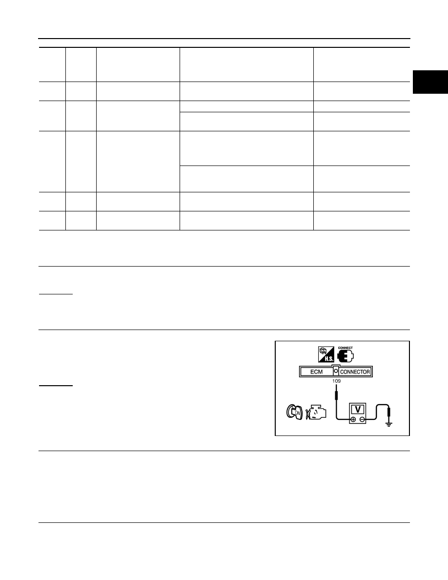
1.
Turn ignition switch OFF and then ON.
2.
Check voltage between ECM terminal 109 and ground with
CONSULT-III or tester.
OK or NG
OK
>> GO TO 4.
NG
>> GO TO 3.
3.
DETECT MALFUNCTIONING PART
Check the following.
• Fuse block (J/B) connector M1
• 15A fuse
• Harness for open or short between ECM and fuse
>> Repair open circuit or short ground or short power in harness or connectors.
4.
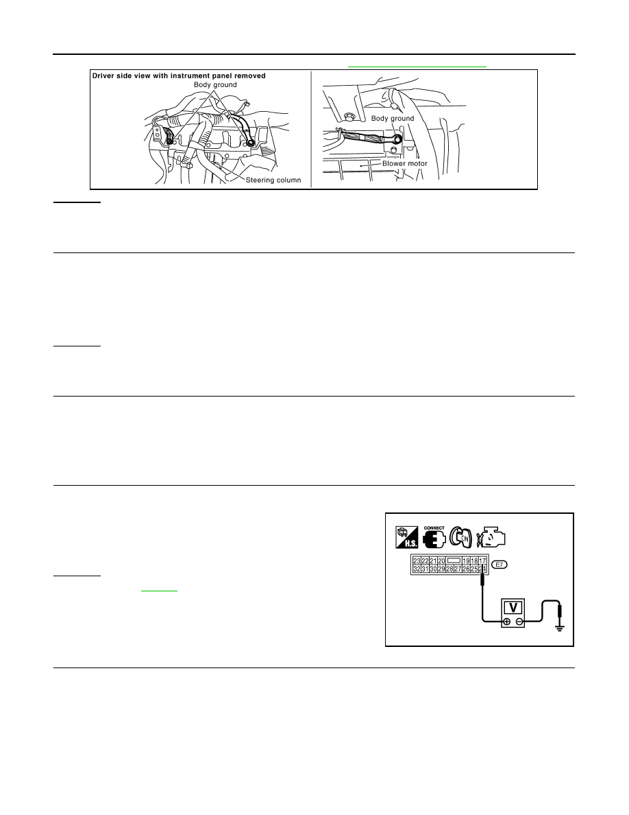
CHECK GROUND CONNECTIONS
1.
Turn ignition switch OFF.
TER-
MI-
NAL
NO.
WIRE
COLOR
ITEM
CONDITION
DATA (DC Voltage)
1
B
ECM ground
[Engine is running]
• Idle speed
Body ground
109
W/L
Ignition switch
[Ignition switch: OFF]
0V
[Ignition switch: ON]
BATTERY VOLTAGE
(11 - 14V)
111
W/B
ECM relay
(Self shut-off)
[Engine is running]
[Ignition switch: OFF]
• For a few seconds after turning ignition
switch OFF
0 - 1.5V
[Ignition switch: OFF]
• More than a few seconds after turning igni-
tion switch OFF
BATTERY VOLTAGE
(11 - 14V)
115
116
B/R
B/W
ECM ground
[Engine is running]
• Idle speed
Body ground
119
120
R
R/B
Power supply for ECM
[Ignition switch: ON]
BATTERY VOLTAGE
(11 - 14V)
Voltage: Battery voltage
MBIB0015E
EC-142
< SERVICE INFORMATION >
[VQ35DE]
POWER SUPPLY AND GROUND CIRCUIT
2.
Loosen and retighten ground screw on the body. Refer to
OK or NG
OK
>> GO TO 5.
NG
>> Repair or replace ground connections.
5.
CHECK ECM GROUND CIRCUIT FOR OPEN AND SHORT-I
1.
Disconnect ECM harness connector.
2.
Check harness continuity between ECM terminals 1, 115, 116 and ground.
Refer to Wiring Diagram.
3.
Also check harness for short to power.
OK or NG
OK
>> GO TO 7.
NG
>> GO TO 6.
6.
DETECT MALFUNCTIONING PART
Check the following.
• Harness connectors F102, M82
• Harness for open or short between ECM and ground
>> Repair open circuit or short to power in harness or connectors.
7.
CHECK ECM POWER SUPPLY CIRCUIT-II
1.
Reconnect ECM harness connector.
2.
Turn ignition switch ON.
3.
Check voltage between IPDM E/R connector E7 terminal 17 and
ground with CONSULT-III or tester.
OK or NG
OK
>> Go to
.
NG
>> GO TO 8.
8.
CHECK ECM POWER SUPPLY CIRCUIT-III
1.
Turn ignition switch OFF and wait at least 10 seconds.
2.
Turn ignition switch ON and then OFF.
PBIB2625E
Continuity should exist.
Voltage: Battery voltage
PBIB1610E
POWER SUPPLY AND GROUND CIRCUIT
EC-143
< SERVICE INFORMATION >
[VQ35DE]
C
D
E
F
G
H
I
J
K
L
M
A
EC
N
P
O
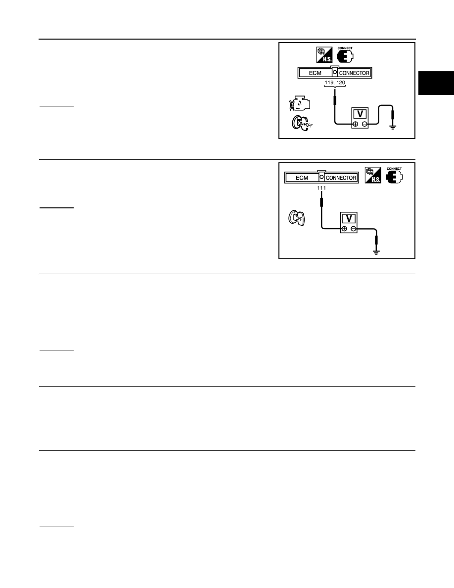
3.
Check voltage between ECM terminals 119, 120 and ground
with CONSULT-III or tester.
OK or NG
OK
>> GO TO 15.
NG (Battery voltage does not exist.)>>GO TO 9.
NG (Battery voltage exists for more than a few seconds.)>>GO TO
12.
9.
CHECK ECM POWER SUPPLY CIRCUIT-IV
Check voltage between ECM terminal 111 and ground with CON-
SULT-III or tester.
OK or NG
OK
>> GO TO 10.
NG
>> GO TO 12.
10.
CHECK ECM POWER SUPPLY CIRCUIT-V
1.
Disconnect ECM harness connector.
2.
Disconnect IPDM E/R harness connector E7.
3.
Check harness continuity between ECM terminals 119, 120 and IPDM E/R terminal 18.
Refer to Wiring Diagram.
4.
Also check harness for short to ground and short to power.
OK or NG
OK
>> GO TO 15.
NG
>> GO TO 11.
11.
DETECT MALFUNCTIONING PART
Check the following.
• Harness or connectors E211, M41
• Harness for open or short between ECM and IPDM E/R
>> Repair open circuit or short to ground or short to power in harness or connectors.
12.
CHECK ECM POWER SUPPLY CIRCUIT-VI
1.
Disconnect ECM harness connector.
2.
Disconnect IPDM E/R harness connector E9.
3.
Check harness continuity between ECM terminal 111 and IPDM E/R terminal 46.
Refer to Wiring Diagram.
4.
Also check harness for short to ground and short to power.
OK or NG
OK
>> GO TO 14.
NG
>> GO TO 13.
13.
DETECT MALFUNCTIONING PART
Voltage:
After turning ignition switch OFF, battery
voltage will exist for a few seconds, then drop
approximately 0V.
PBIB1630E
Voltage: Battery voltage
PBIB1191E
Continuity should exist.
Continuity should exist.
EC-144
< SERVICE INFORMATION >
[VQ35DE]
POWER SUPPLY AND GROUND CIRCUIT
Check the following.
• Harness or connectors E211, M41
• Harness for open or short between ECM and IPDM E/R
>> Repair open circuit or short to ground or short to power in harness or connectors.
14.
CHECK 20A FUSE
1.
Disconnect 20 A fuse from IPDM E/R.
2.
Check 20A fuse.
OK or NG
OK
>> GO TO 18.
NG
>> Replace 20A fuse.
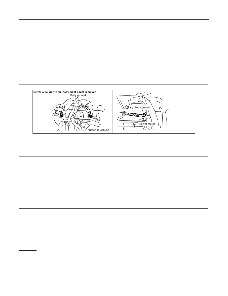
15.
CHECK GROUND CONNECTIONS
Loosen and retighten ground screw on the body. Refer to
OK or NG
OK
>> GO TO 16.
NG
>> Repair or replace ground connections.
16.
CHECK ECM GROUND CIRCUIT FOR OPEN AND SHORT-II
1.
Disconnect ECM harness connector.
2.
Check harness continuity between ECM terminals 1, 115, 116 and ground.
Refer to Wiring Diagram.
3.
Also check harness for short to power.
OK or NG
OK
>> GO TO 17.
NG
>> Repair open circuit or short to power in harness or connectors.
17.
DETECTION MALFUNCTIONING PART
Check the following.
• Harness connectors F102, M82
• Harness for open or short between ECM and ground
>> Repair open circuit or shoat to power in harness connectors.
18.
CHECK INTERMITTENT INCIDENT
OK or NG
OK
>> Replace IPDM E/R. Refer to
NG
>> Repair open circuit or short to power in harness or connectors.
Ground Inspection
INFOID:0000000001325948
Ground connections are very important to the proper operation of electrical and electronic circuits. Ground
connections are often exposed to moisture, dirt and other corrosive elements. The corrosion (rust) can
become an unwanted resistance. This unwanted resistance can change the way a circuit works.
PBIB2625E
Continuity should exist.
Нет комментариевНе стесняйтесь поделиться с нами вашим ценным мнением.
Текст