Infiniti FX35 / FX45. Manual — part 346
POWER SUPPLY AND GROUND CIRCUIT
EC-145
< SERVICE INFORMATION >
[VQ35DE]
C
D
E
F
G
H
I
J
K
L
M
A
EC
N
P
O
Electronically controlled circuits are very sensitive to proper grounding. A loose or corroded ground can drasti-
cally affect an electronically controlled circuit. A poor or corroded ground can easily affect the circuit. Even
when the ground connection looks clean, there can be a thin film of rust on the surface.
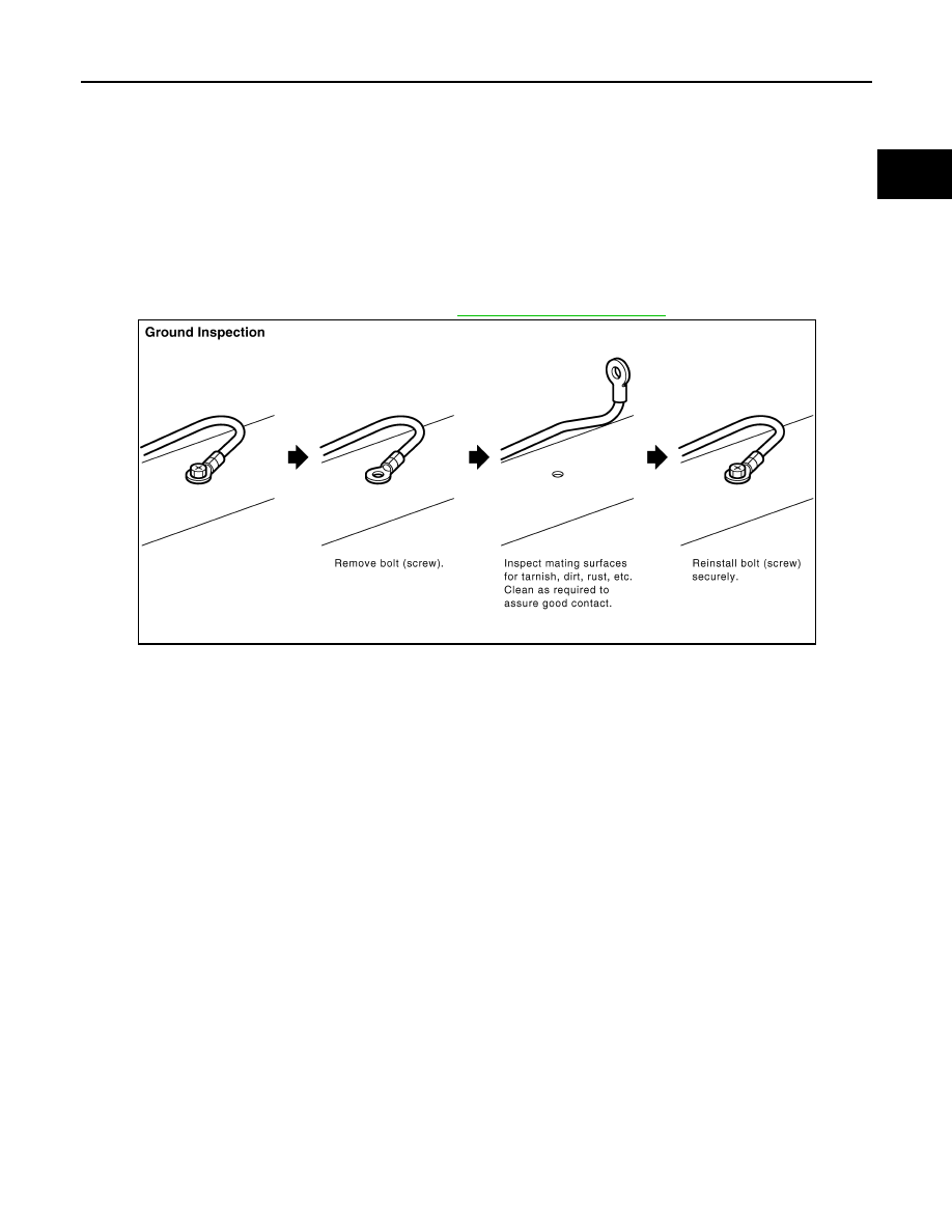
When inspecting a ground connection follow these rules:
• Remove the ground bolt or screw.
• Inspect all mating surfaces for tarnish, dirt, rust, etc.
• Clean as required to assure good contact.
• Reinstall bolt or screw securely.
• Inspect for “add-on” accessories which may be interfering with the ground circuit.
• If several wires are crimped into one ground eyelet terminal, check for proper crimps. Make sure all of the
wires are clean, securely fastened and providing a good ground path. If multiple wires are cased in one eye-
let make sure no ground wires have excess wire insulation.
For detailed ground distribution information, refer to
PBIB1870E

EC-146
< SERVICE INFORMATION >
[VQ35DE]
DTC U1000, U1001 CAN COMMUNICATION LINE
DTC U1000, U1001 CAN COMMUNICATION LINE
Description
INFOID:0000000001325949
CAN (Controller Area Network) is a serial communication line for real time application. It is an on-vehicle mul-
tiplex communication line with high data communication speed and excellent error detection ability. Many elec-
tronic control units are equipped onto a vehicle, and each control unit shares information and links with other
control units during operation (not independent). In CAN communication, control units are connected with 2
communication lines (CAN H line, CAN L line) allowing a high rate of information transmission with less wiring.
Each control unit transmits/receives data but selectively reads required data only.
On Board Diagnosis Logic
INFOID:0000000001325950
*1: This self-diagnosis has the one trip detection logic.
*2: The MIL will not light up for this self-diagnosis.
*3: This self-diagnosis has the one or two trip detection logic. (Models with ICC)
DTC Confirmation Procedure
INFOID:0000000001325951
1.
Turn ignition switch ON and wait at least 3 seconds.
2.
Check 1st tip DTC.
3.
If 1st trip DTC is detected, go to
DTC No.
Trouble diagnosis
name
DTC detecting condition
Possible cause
U1000*
1
1000*
1
CAN communication
line
• When ECM is not transmitting or receiving
CAN communication signal of OBD (emission-
related diagnosis) for 2 seconds or more.
• Harness or connectors
(CAN communication line is open or
shorted)
U1001*
2
*
3
1001*
2
*
3
• When ECM is not transmitting or receiving
CAN communication signal other than OBD
(emission-related diagnosis) for 2 seconds or
more.
DTC U1000, U1001 CAN COMMUNICATION LINE
EC-147
< SERVICE INFORMATION >
[VQ35DE]
C
D
E
F
G
H
I
J
K
L
M
A
EC
N
P
O
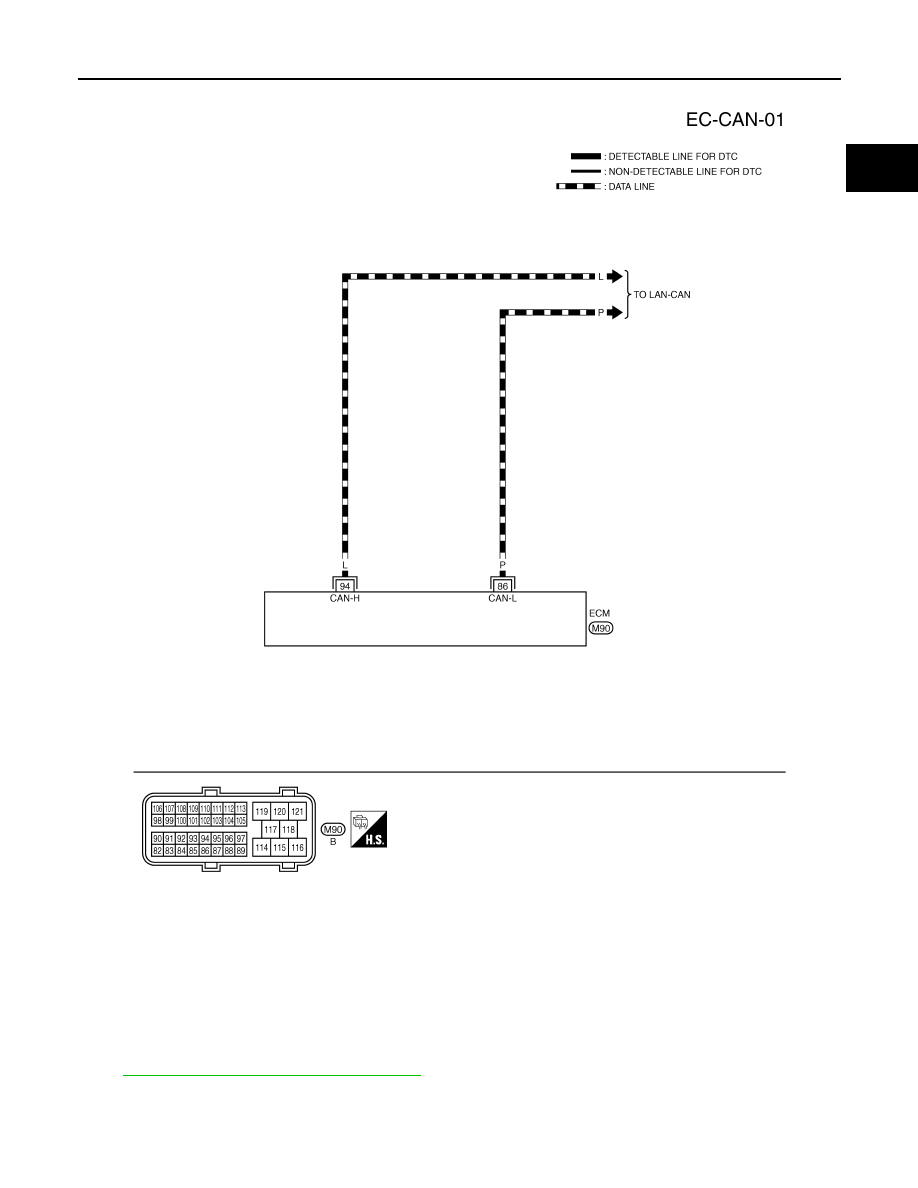
Wiring Diagram
INFOID:0000000001325952
Diagnosis Procedure
INFOID:0000000001325953
LAN-43, "CAN System Specification Chart"
.
TBWM1378E

EC-148
< SERVICE INFORMATION >
[VQ35DE]
DTC U1010 CAN COMMUNICATION
DTC U1010 CAN COMMUNICATION
Description
INFOID:0000000001325954
CAN (Controller Area Network) is a serial communication line for real time application. It is an on-vehicle mul-
tiplex communication line with high data communication speed and excellent error detection ability. Many elec-
tronic control units are equipped onto a vehicle, and each control unit shares information and links with other
control units during operation (not independent). In CAN communication, control units are connected with 2
communication lines (CAN H line, CAN L line) allowing a high rate of information transmission with less wiring.
Each control unit transmits/receives data but selectively reads required data only.
On Board Diagnosis Logic
INFOID:0000000001325955
This self-diagnosis has the one trip detection logic.
DTC Confirmation Procedure
INFOID:0000000001325956
1.
Turn ignition switch ON.
2.
Check DTC.
3.
If DTC is detected, go to
.
Diagnosis Procedure
INFOID:0000000001325957
1.
INSPECTION START
With CONSULT-III
1.
Turn ignition switch ON.
2.
Select “SELF-DIAG RESULTS” mode with CONSULT-III.
3.
Touch “ERASE”.
4.
Perform DTC Confirmation Procedure.
See
EC-148, "DTC Confirmation Procedure"
5.
Is the DTC U1010 displayed again?
With GST
1.
Turn ignition switch ON.
2.
Select Service $04 with GST.
3.
Perform DTC Confirmation Procedure.
See
EC-148, "DTC Confirmation Procedure"
4.
Is the DTC U1010 displayed again?
Yes or No
Yes
>> GO TO 2.
No
>> INSPECTION END
2.
REPLACE ECM
1.
Replace ECM.
2.
Perform initialization of IVIS (NATS) system and registration of all IVIS (NATS) ignition key IDs.
Refer to
BL-187, "ECM Re-Communicating Function"
3.
4.
EC-85, "Accelerator Pedal Released Position Learning"
5.
EC-85, "Throttle Valve Closed Position Learning"
.
6.
EC-85, "Idle Air Volume Learning"
>> INSPECTION END
DTC No.
Trouble diagnosis name
DTC detecting condition
Possible cause
U1010
1010
CAN communication bus
When detecting error during the initial diagno-
sis of CAN controller of ECM.
• ECM
Нет комментариевНе стесняйтесь поделиться с нами вашим ценным мнением.
Текст