Infiniti FX35 / FX45. Manual — part 696
FAX-20
< SERVICE INFORMATION >
[AWD]
FRONT DRIVE SHAFT
Housing and spider assembly are components which are used as a set.
ASSEMBLY
Front Final Drive Assembly Side
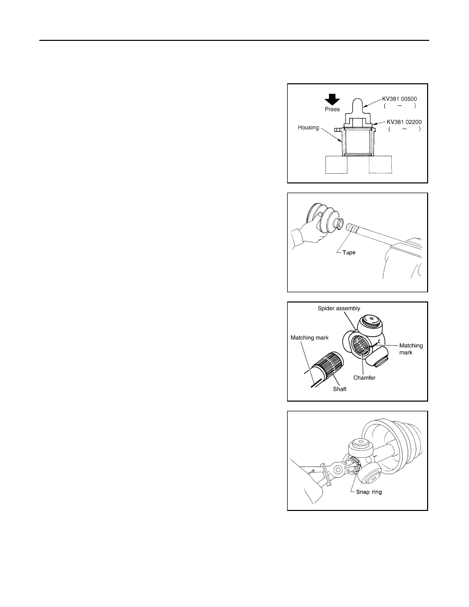
1.
If plug has been removed, use a drift (SST) to press in a new
one.
NOTE:
Discard old plug; replace with new ones.
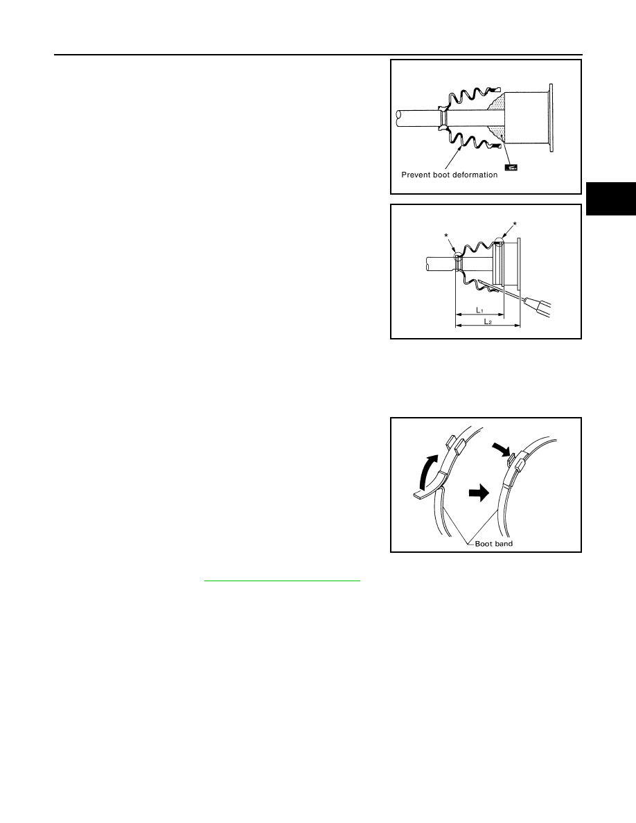
2.
Wind serrated part of shaft with tape. Install boot band and boot
to shaft. Be careful not to damage boot.
NOTE:
Discard old boot band and boot; replace with each new one.
3.
Remove protective tape wound around serrated part of shaft.
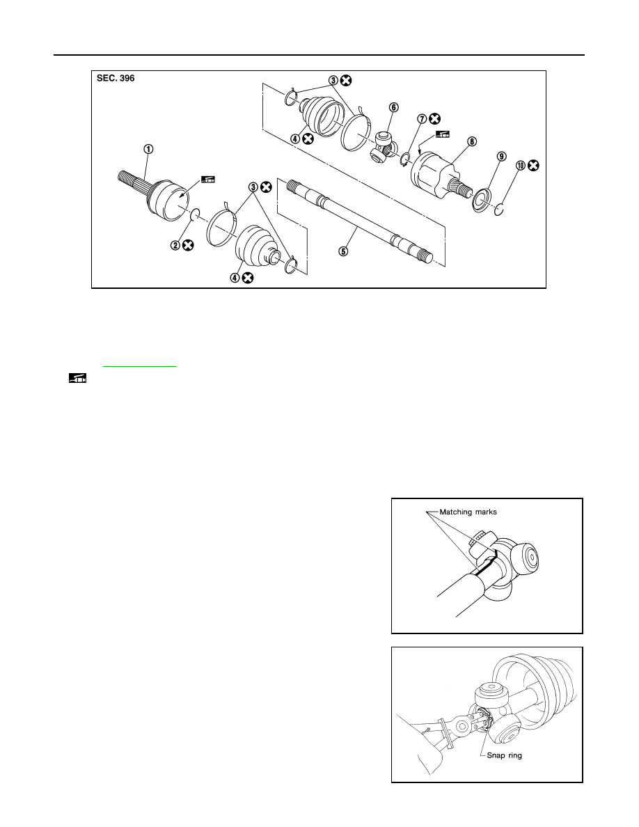
4.
Line up alignment marks which were made when spider assem-
bly was removed. Install spider assembly, with serration chamfer
facing shaft.
5.
Secure spider assembly with snap ring.
NOTE:
Discard old snap ring; replace with new one.
6.
Apply Nissan genuine grease or equivalent to spider assembly
and sliding surface.
SDIA1153E
SFA800
SDIA2629E
SFA023A
FRONT DRIVE SHAFT
FAX-21
< SERVICE INFORMATION >
[AWD]
C
E
F
G
H
I
J
K
L
M
A
B
FAX
N
O
P
7.
Install housing to spider assembly. Apply Nissan genuine grease
or equivalent to housing.
8.
Install boot securely into grooves (indicated by *marks) shown in
the figure.
CAUTION:
If there is grease on boot mounting surfaces (indicated by *
marks) of shaft and housing, boot may come off. Remove
all grease from surfaces.
9.
Make sure boot installation length “L
1
L
2
” is the length indicated
below. Insert a flat-bladed screwdriver or similar tool into smaller
side of boot. Bleed air from boot to prevent boot deformation.
CAUTION:
• Boot may break if boot installation length is less than standard value.
• Take care not to touch the tip of screwdriver to inside surface of boot.
10. Install new larger and smaller boot bands securely.
NOTE:
Discard old boot bands; replace with new ones.
11. After installing housing and shaft, rotate boot to check whether
or not the actual position is correct. If boot position is not correct,
secure boot with new boot bands again.
12. Install circular clip.
NOTE:
Discard old circular clip; replace with new one.
Wheel Side
Assemble in steps 14 to 23 of
FAX-13, "On-Vehicle Inspection"
Disassembly and Assembly (Right Side)
INFOID:0000000001327519
COMPONENTS
Grease amount
: 95
−
105 g (3.35
−
3.70 oz)
SDIA1445E
Boot installation Length “L
1
L
2
”:
VK45DE models (L
1
)
: 95
−
97 mm (3.74
−
3.82 in)
VQ35DE models (L
2
)
: 150.9
−
152.9 mm (5.94
−
6.02 in)
PDIA1255E
SFA395
FAX-22
< SERVICE INFORMATION >
[AWD]
FRONT DRIVE SHAFT
DISASSEMBLY
Front Final Drive Assembly Side
1.
Press drive shaft in a vice.
CAUTION:
When retaining drive shaft in a vice, always use copper or aluminum plates between a vise and
shaft.
2.
Remove boot bands.
3.
Put matching marks on spider assembly and shaft.
CAUTION:
Use paint for matching mark, but don’t damage to spider
assembly and shaft.
4.
Remove snap ring, then remove spider assembly from shaft.
5.
Remove boot from shaft.
6.
Remove old grease on slide joint assembly with paper towels.
1.
Joint sub-assembly
2.
Circular clip
3.
Boot band
4.
Boot
5.
Shaft
6.
Spider assembly
7.
Snap ring
8.
Housing
9.
Dust shield
10.
Circular clip
Refer to
and the following for the symbols in the figure.
: Fill NiSSAN genuine grease or equivalent.
PDIA1221E
SFA963
SFA612
FRONT DRIVE SHAFT
FAX-23
< SERVICE INFORMATION >
[AWD]
C
E
F
G
H
I
J
K
L
M
A
B
FAX
N
O
P
Wheel Side
1.
Place drive shaft in a vice.
CAUTION:
When retaining drive shaft in a vice, always use copper or aluminum plates between vise a and
shaft.
2.
Remove boot bands. Then remove boot from joint sub-assembly.
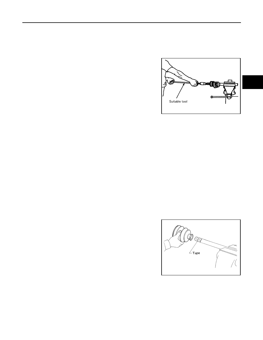
3.
Screw a drive shaft puller (suitable tool) 30 mm (1.18 in) or more
into threaded part of joint sub-assembly. Pull joint sub-assembly
out of shaft.
CAUTION:
• If joint sub-assembly cannot be removed after five or
more unsuccessful attempts, replace shaft and joint sub-
assembly as a set.
• Align sliding hammer and drive shaft and remove them by
pulling directly.
4.
Remove boot from shaft.
5.
Remove circular clip from shaft.
6.
While rotating ball cage, remove old grease on joint sub-assem-
bly with paper towels.
INSPECTION AFTER DISASSEMBLY
Shaft
Replace shaft if there is any runout, cracking, or other damage.
Joint Sub-Assembly
• Make sure there is no rough rotation or unusual axial looseness.
• Make sure there is no foreign material inside joint sub-assembly.
• Check joint sub-assembly for compression scar, cracks or fractures.
• If there are any irregular conditions of joint sub-assembly components, replace the entire joint sub-assembly.
Slide Joint Side
Housing and spider assembly
• If roller or roller surface of spider assembly has scratch or wear, replace housing and spider assembly.
NOTE:
Housing and spider assembly are components which are used as a set.
ASSEMBLY
Front Final Drive Assembly Side
1.
Wind serrated part of drive shaft with tape. Install boot band and
boot to shaft. Be careful not to damage boot.
NOTE:
Discard old boot band and boot; replace with each new one.
2.
Remove protective tape wound around serrated part of shaft.
SDIA0606E
SFA800
Нет комментариевНе стесняйтесь поделиться с нами вашим ценным мнением.
Текст