Infiniti FX35 / FX45. Manual — part 695
FAX-16
< SERVICE INFORMATION >
[AWD]
FRONT DRIVE SHAFT
2.
Remove undercover with power tool.
3.
Remove cotter pin. Then remove lock nut from drive shaft with power tool.
4.
Remove wheel sensor harness from strut assembly. Refer to
CAUTION:
Do not pull on wheel sensor harness.
5.
Remove brake hose lock plate. Then remove brake hose from strut assembly. Refer to
.
6.
Remove fixing bolts and nuts between strut assembly and steering knuckle with power tool.
7.
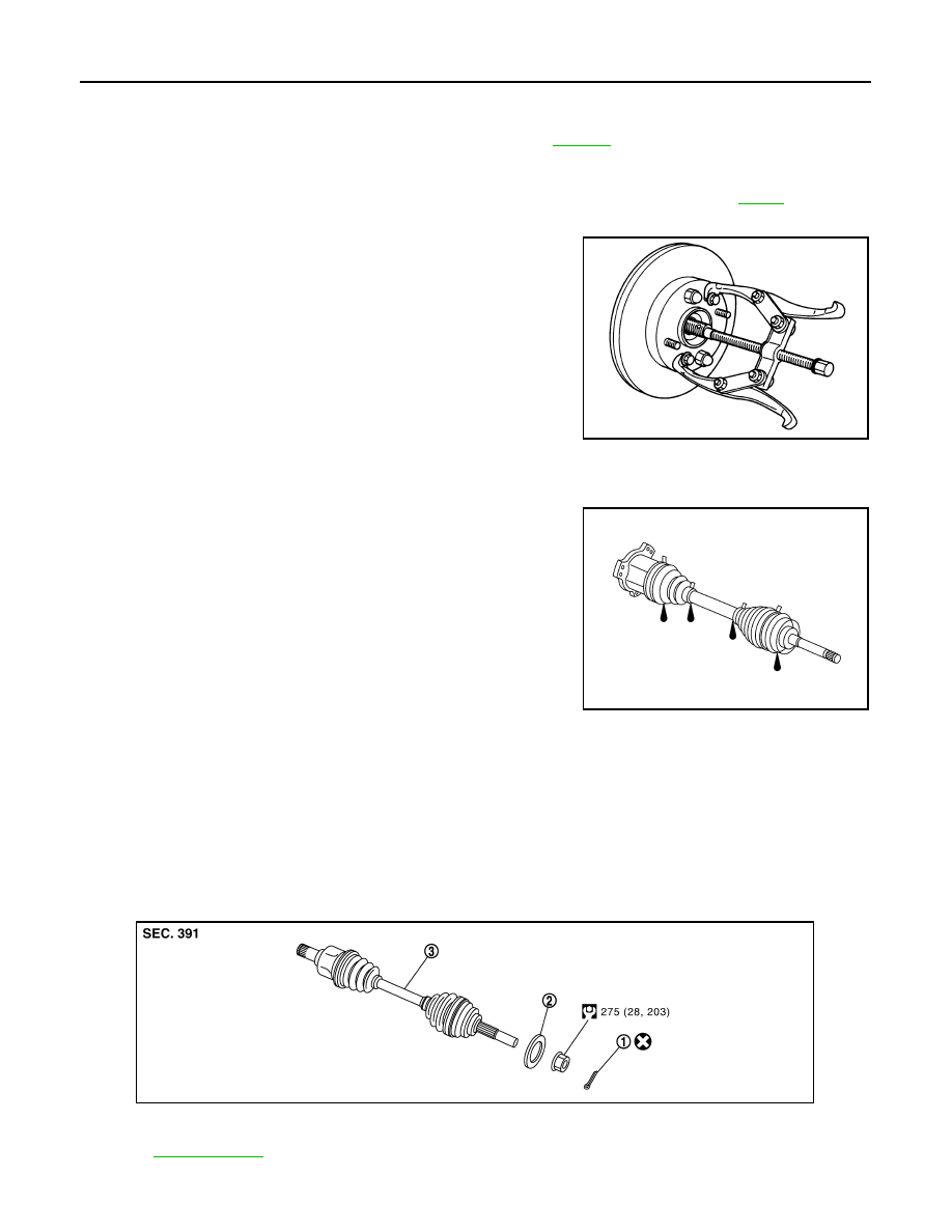
Using a puller (suitable tool), remove drive shaft from steering
knuckle.
CAUTION:
When removing drive shaft, do not apply an excessive
angle to drive shaft joint. Also be careful not to excessively
extend slide joint.
8.
Remove fixing bolt of front final drive side assembly drive shaft
with power tool, then remove drive shaft from vehicle.
INSPECTION AFTER REMOVAL
• Move joint up/down, left /right, and in the axial direction. Check for any rough movement or significant loose-
ness.
• Check boot for cracks or other damage, and also for grease leak-
age.
• If a trouble is found, disassemble drive shaft, and then replace with
new one.
INSTALLATION
• Refer to "Removal and Installation (Left Side)" for tightening torque. Install in the reverse order of removal.
NOTE:
Refer to component parts location and do not reuse non-reusable parts.
• Check the following item after service.
- Installation condition of wheel sensor harness
Removal and Installation (Right Side)
INFOID:0000000001327517
COMPONENTS
SDIA0972J
SDIA1046J
1.
Cotter pin
2.
Washer
3.
Drive shaft
Refer to
, for the symbols in the figure.
PDIA1219E
FRONT DRIVE SHAFT
FAX-17
< SERVICE INFORMATION >
[AWD]
C
E
F
G
H
I
J
K
L
M
A
B
FAX
N
O
P
Removal
1.
Remove tires from vehicle with power tool.
2.
Remove undercover with power tool.
3.
Remove cotter pin. Then remove lock nut from drive shaft with power tool.
4.
Remove wheel sensor harness from strut assembly. Refer to
.
CAUTION:
Do not pull on wheel sensor harness.
5.
Remove brake hose lock prate. Then remove brake hose from strut assembly. Refer to
6.
Remove fixing bolts and nuts between strut assembly and steering knuckle with power tool.
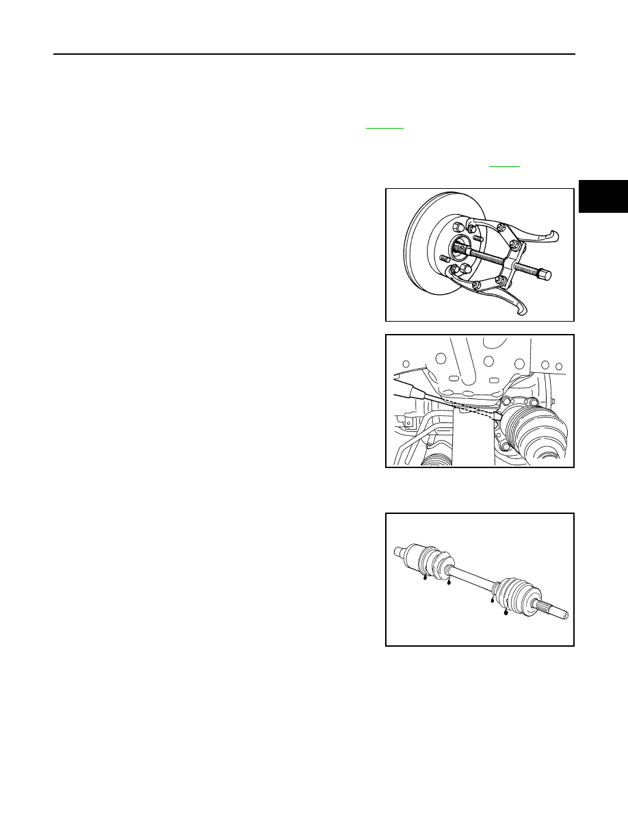
7.
Using a puller (suitable tool), remove drive shaft from steering
knuckle.
CAUTION:
When removing drive shaft, do not apply an excessive
angle to drive shaft joint. Also be careful not to excessively
extend slide joint.
8.
Pry off drive shaft from front final drive assembly side as shown
in the figure.
INSPECTION AFTER REMOVAL
• Move joint up/down, left/right, and in the axial direction. Check for any rough movement or significant loose-
ness.
• Check boot for cracks or other damage, and also for grease leak-
age.
• If a trouble is found, disassemble drive shaft, and then replace with
new one.
INSTALLATION
• Refer to "Removal and installation (Right Side)" for tightening torque. Install in the reverse order of removal.
NOTE:
Refer to component parts location and do not reuse non-reusable parts.
• Check the following item after service.
- Installation condition of wheel sensor harness.
SDIA0972J
SDIA1489E
SFA108A
FAX-18
< SERVICE INFORMATION >
[AWD]
FRONT DRIVE SHAFT
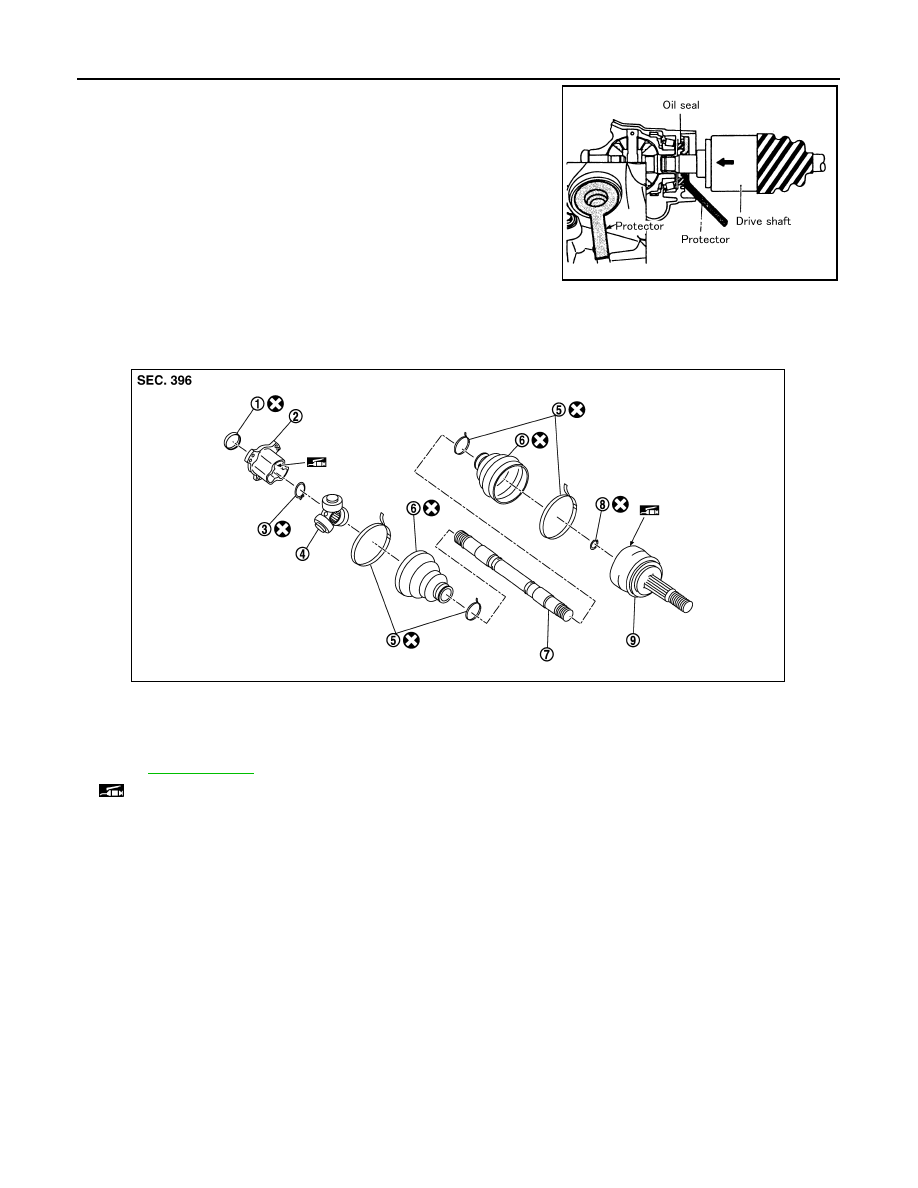
• Place the protector [SST: KV38107900 (
–
)] onto front final
drive assembly to prevent damage to the oil seal while inserting
drive shaft. Slide drive shaft sliding joint and tap with a hammer to
install securely. (right side)
CAUTION:
Be sure to check that circular clip is securely fastened.
Disassembly and Assembly (Left Side)
INFOID:0000000001327518
COMPONENTS
DISASSEMBLY
Front Final Drive Assembly Side
1.
Press drive shaft in a vice.
CAUTION:
When retaining shaft in a vice, always use copper or aluminum plates between vise and shaft.
2.
Remove boot bands.
3.
If plug needs to be removed, move boot to wheel side, and drive it out with a plastic hammer.
SDIA0593E
1.
Plug
2.
Housing 3.
Snap
ring
4.
Spider assembly
5.
Boot band
6.
Boot
7.
Shaft
8.
Circular clip
9.
Joint sub-assembly
Refer to
and the following for the symbols in the figure.
: Fill Nissan genuine grease or equivalent.
PDIA1220E
FRONT DRIVE SHAFT
FAX-19
< SERVICE INFORMATION >
[AWD]
C
E
F
G
H
I
J
K
L
M
A
B
FAX
N
O
P
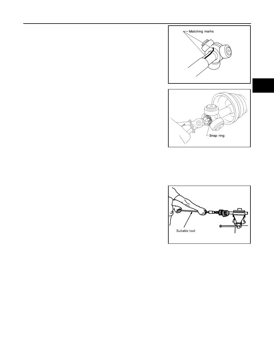
4.
Put matching marks on spider assembly and shaft.
CAUTION:
Use paint for matching mark, but don’t damage to spider
assembly and drive shaft.
5.
Remove snap ring, then remove spider assembly from shaft.
6.
Remove boot from shaft.
7.
Remove old grease on slide joint assembly with paper towels.
Wheel Side
1.
Place drive shaft in a vice.
CAUTION:
When retaining drive shaft in a vice, always use copper or aluminum plates between a vise and
shaft.
2.
Remove boot bands. Then remove boot from joint sub-assembly.
3.
Screw a drive shaft puller (suitable tool) 30 mm (1.18 in) or more
into threaded part of joint sub-assembly. Pull joint sub-assembly
out of shaft.
CAUTION:
• If joint sub-assembly cannot be removed after five or
more unsuccessful attempts, replace shaft and joint sub-
assembly as a set.
• Align sliding hammer and drive shaft and remove them by
pulling directly.
4.
Remove boot from shaft.
5.
Remove circular clip from shaft.
6.
While rotating ball cage, remove old grease on joint sub-assem-
bly with paper towels.
INSPECTION AFTER DISASSEMBLY
Shaft
Replace shaft if there is any runout, cracking, or other damage.
Joint Sub-Assembly
• Make sure there is no rough rotation or unusual axial looseness.
• Make sure there is no foreign material inside joint sub-assembly.
• Check joint sub-assembly for compression scar, cracks or fractures.
CAUTION:
If there are any irregular conditions of joint sub-assembly components, replace the entire joint sub-
assembly.
Slide Joint Side
Housing and spider assembly
• If roller or roller surface of spider assembly has scratch or wear, replace housing and spider assembly.
NOTE:
SFA963
SFA612
SDIA0606E
Нет комментариевНе стесняйтесь поделиться с нами вашим ценным мнением.
Текст