Infiniti FX35 / FX45. Manual — part 865
PS-2
< SERVICE INFORMATION >
PRECAUTIONS
SERVICE INFORMATION
PRECAUTIONS
Precaution for Supplemental Restraint System (SRS) "AIR BAG" and "SEAT BELT
PRE-TENSIONER"
INFOID:0000000001612911
The Supplemental Restraint System such as “AIR BAG” and “SEAT BELT PRE-TENSIONER”, used along
with a front seat belt, helps to reduce the risk or severity of injury to the driver and front passenger for certain
types of collision. This system includes seat belt switch inputs and dual stage front air bag modules. The SRS
system uses the seat belt switches to determine the front air bag deployment, and may only deploy one front
air bag, depending on the severity of a collision and whether the front occupants are belted or unbelted.
Information necessary to service the system safely is included in the “SUPPLEMENTAL RESTRAINT SYS-
TEM” and “SEAT BELTS” of this Service Manual.
WARNING:
• To avoid rendering the SRS inoperative, which could increase the risk of personal injury or death in
the event of a collision which would result in air bag inflation, all maintenance must be performed by
an authorized NISSAN/INFINITI dealer.
• Improper maintenance, including incorrect removal and installation of the SRS, can lead to personal
injury caused by unintentional activation of the system. For removal of Spiral Cable and Air Bag
Module, see the “SUPPLEMENTAL RESTRAINT SYSTEM”.
• Do not use electrical test equipment on any circuit related to the SRS unless instructed to in this
Service Manual. SRS wiring harnesses can be identified by yellow and/or orange harnesses or har-
ness connectors.
Precaution Necessary for Steering Wheel Rotation After Battery Disconnect
INFOID:0000000001612914
NOTE:
• This Procedure is applied only to models with Intelligent Key system and NVIS/IVIS (NISSAN/INFINITI
VEHICLE IMMOBILIZER SYSTEM - NATS).
• Remove and install all control units after disconnecting both battery cables with the ignition knob in the
″
LOCK
″
position.
• Always use CONSULT-III to perform self-diagnosis as a part of each function inspection after finishing work.
If DTC is detected, perform trouble diagnosis according to self-diagnostic results.
For models equipped with the Intelligent Key system and NVIS/IVIS, an electrically controlled steering lock
mechanism is adopted on the key cylinder.
For this reason, if the battery is disconnected or if the battery is discharged, the steering wheel will lock and
steering wheel rotation will become impossible.
If steering wheel rotation is required when battery power is interrupted, follow the procedure below before
starting the repair operation.
OPERATION PROCEDURE
1.
Connect both battery cables.
NOTE:
Supply power using jumper cables if battery is discharged.
2.
Use the Intelligent Key or mechanical key to turn the ignition switch to the
″
ACC
″
position. At this time, the
steering lock will be released.
3.
Disconnect both battery cables. The steering lock will remain released and the steering wheel can be
rotated.
4.
Perform the necessary repair operation.
5.
When the repair work is completed, return the ignition switch to the
″
LOCK
″
position before connecting
the battery cables. (At this time, the steering lock mechanism will engage.)
6.
Perform a self-diagnosis check of all control units using CONSULT-III.
Precaution for Steering System
INFOID:0000000001327705
• In case of removing steering gear assembly, make the final tightening with grounded and unloaded vehicle
condition, and then check wheel alignment.
• Observe the following precautions when disassembling.
PRECAUTIONS
PS-3
< SERVICE INFORMATION >
C
D
E
F
H
I
J
K
L
M
A
B
PS
N
O
P
- Before disassembly, thoroughly clean the outside of the unit.
- Disassembly should be done in a clean work area. It is important to prevent the internal parts from becoming
contaminated by dirt or other foreign matter.
- For easier and proper assembly, place disassembled parts in order on a parts rack.
- Use nylon cloth or paper towels to clean the parts; common shop rags can leave lint that might interfere with
their operation.
- Do not reuse non-reusable parts.
- Before assembling, apply the specified grease to the directed parts.
PS-4
< SERVICE INFORMATION >
PREPARATION
PREPARATION
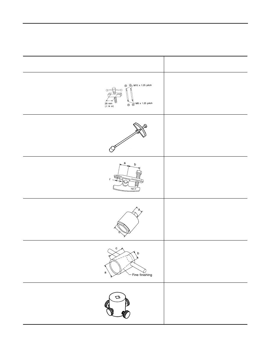
Special Service Tool
INFOID:0000000001327706
The actual shapes of Kent-Moore tools may differ from those of special service tools illustrated here.
Tool number
(Kent-Moore No.)
Tool name
Description
ST27180001(J-25726-A)
Removing steering wheel
ST3127S000
(J-25765-A)
Preload gauge
Inspecting of sliding torque, steering torque,
and rotating torque for ball joint
HT72520000
(J-25730-A)
Ball joint remover
a: 33 mm (1.3 in)
b: 50 mm (1.97 in)
r: 11.5 mm (0.45 in)
Removing steering outer socket
KV4810 5400
(J-46213)
Rear cover wrench
a: 21.6 mm (0.85 in)
b: 34.9 mm (1.37 in)
Removing rear cover
KV48104400
( — )
Teflon ring correcting tool
a: 50 mm (1.97 in) dia.
b: 36 mm (1.42 in) dia.
c: 100 mm (3.94 in)
Installing of rack Teflon ring
KV48103400
( — )
Torque adapter
Inspecting rotating torque
S-NT544
ZZA0806D
NT546
SGIA0516E
S-NT550
ZZA0824D
PREPARATION
PS-5
< SERVICE INFORMATION >
C
D
E
F
H
I
J
K
L
M
A
B
PS
N
O
P
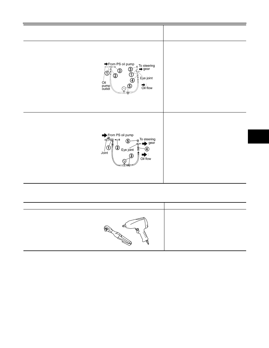
Commercial Service Tool
INFOID:0000000001327707
1. KV48102500-04
( — )
Washer
2. KV48102500-01
( — )
Eye joint
3. KV48102500-03
( — )
Bolt
4. KV48102500-02
( — )
Flare Joint
5. KV48103500
(J-26357&J-26357-10)
Pressure gauge & shut off valve
Measuring oil pump relief pressure
(VQ35DE models)
1. KV48105300-4 and 5295262U10
( — )
Connector A and O-ring
2. KV48105300-3 and 5295262U00
( — )
Eye-bolt and O-ring
3. KV48103500
(J-26357 and J-26357-10)
Pressure gauge and shut-off valve
4. KV48105300-1 and 5295262U00
( — )
Connector B and O-ring
5. KV48105300-2
( — )
Nut
Measuring oil pump relief pressure
(VK45DE models)
Tool number
(Kent-Moore No.)
Tool name
Description
SGIA0442E
SGIA0427E
Tool name
Description
Power tool
Loosening bolts and nuts
PBIC0190E
Нет комментариевНе стесняйтесь поделиться с нами вашим ценным мнением.
Текст