Infiniti FX35 / FX45. Manual — part 758
TROUBLE DIAGNOSIS
LAN-9
< SERVICE INFORMATION >
[CAN FUNDAMENTAL]
C
D
E
F
G
H
I
J
L
M
A
B
LAN
N
O
P
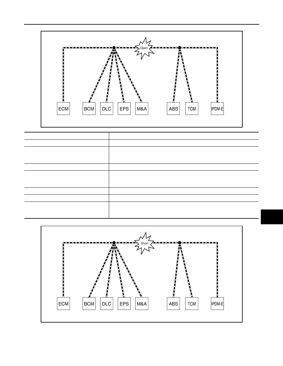
Example: Main Line Between Data Link Connector and ABS Actuator and Electric Unit (Control Unit) Open Circuit
Example: CAN-H, CAN-L Harness Short Circuit
SKIB8740E
Unit name
Symptom
ECM
Engine torque limiting is affected, and shift harshness increases.
BCM
• Reverse warning chime does not sound.
• The front wiper moves under continuous operation mode even though the front wip-
er switch being in the intermittent position.
EPS control unit
The steering effort increases.
Combination meter
• The shift position indicator and OD OFF indicator turn OFF.
• The speedometer is inoperative.
• The odo/trip meter stops.
ABS actuator and electric unit (control unit)
Normal operation.
TCM
No impact on operation.
IPDM E/R
When the ignition switch is ON,
• The headlamps (Lo) turn ON.
• The cooling fan continues to rotate.
SKIB8741E

LAN-10
< SERVICE INFORMATION >
[CAN FUNDAMENTAL]
TROUBLE DIAGNOSIS
Self-Diagnosis
INFOID:0000000001451950
CAN Diagnostic Support Monitor
INFOID:0000000001451951
CONSULT-III and CAN diagnostic support monitor (on-board diagnosis function) are used for detecting root
cause.
MONITOR ITEM (CONSULT-III)
Unit name
Symptom
ECM
• Engine torque limiting is affected, and shift harshness increases.
• Engine speed drops.
BCM
• Reverse warning chime does not sound.
• The front wiper moves under continuous operation mode even though the front
wiper switch being in the intermittent position.
• The room lamp does not turn ON.
• The engine does not start (if an error or malfunction occurs while turning the igni-
tion switch OFF.)
• The steering lock does not release (if an error or malfunction occurs while turning
the ignition switch OFF.)
EPS control unit
The steering effort increases.
Combination meter
• The tachometer and the speedometer do not move.
• Warning lamps turn ON.
• Indicator lamps do not turn ON.
ABS actuator and electric unit (control unit)
Normal operation.
TCM
No impact on operation.
IPDM E/R
When the ignition switch is ON,
• The headlamps (Lo) turn ON.
• The cooling fan continues to rotate.
DTC
Self-diagnosis item
(CONSULT-III indication)
DTC detection condition
Inspection/Action
U1000
CAN COMM CIRCUIT
When ECM is not transmitting or receiving CAN
communication signal of OBD (emission-related
diagnosis) for 2 seconds or more.
Refer to
When a control unit (except for ECM) is not
transmitting or receiving CAN communication
signal for 2 seconds or more.
U1001
CAN COMM CIRCUIT
When ECM is not transmitting or receiving CAN
communication signal other than OBD (emis-
sion-related diagnosis) for 2 seconds or more.
U1002
SYSTEM COMM
When a control unit is not transmitting or receiv-
ing CAN communication signal for 2 seconds or
less.
Start the inspection. Re-
fer to the applicable sec-
tion of the indicated
control unit.
U1010
CONTROL UNIT [CAN]
When an error is detected during the initial diag-
nosis for CAN controller of each control unit.
Replace the control unit
indicating “U1010”.
TROUBLE DIAGNOSIS
LAN-11
< SERVICE INFORMATION >
[CAN FUNDAMENTAL]
C
D
E
F
G
H
I
J
L
M
A
B
LAN
N
O
P
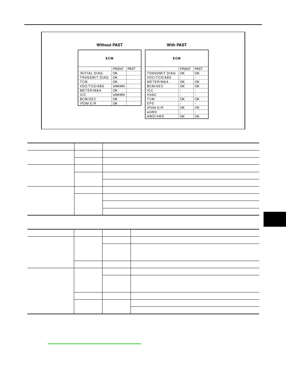
Example: CAN DIAG SUPPORT MNTR indication
Without PAST
With PAST
MONITOR ITEM (ON-BOARD DIAGNOSIS)
NOTE:
• For some models, CAN communication diagnosis result is received from the vehicle monitor. (CONSULT-III
is not available.)
• Refer to
LAN-39, "CAN Diagnostic Support Monitor"
for the details.
PKID1075E
Item
PRSNT
Description
Initial diagnosis
OK
Normal at present
NG
Control unit error (Except for some control units)
Transmission diagnosis
OK
Normal at present
UNKWN
Unable to transmit signals for 2 seconds or more.
Diagnosis not performed
Control unit name
(Reception diagnosis)
OK
Normal at present
UNKWN
Unable to receive signals for 2 seconds or more.
Diagnosis not performed
No control unit for receiving signals. (No applicable optional parts)
Item
PRSNT
PAST
Description
Transmission diagnosis
OK
OK
Normal at present and in the past
1 – 39
Normal at present, but unable to transmit signals for 2 seconds or more
in the past. (The number indicates the number of ignition switch cycles
from OFF to ON.)
UNKWN
0
Unable to transmit signals for 2 seconds or more at present.
Control unit name
(Reception diagnosis)
OK
OK
Normal at present and in the past
1 – 39
Normal at present, but unable to receive signals for 2 seconds or more
in the past. (The number indicates the number of ignition switch cycles
from OFF to ON.)
UNKWN
0
Unable to receive signals for 2 seconds or more at present.
–
–
Diagnosis not performed.
No control unit for receiving signals. (No applicable optional parts)

LAN-12
< SERVICE INFORMATION >
[CAN FUNDAMENTAL]
TROUBLE DIAGNOSIS
Example: Vehicle Display
Item
Result indi-
cated
Error counter
Description
CAN_COMM
(Initial diagnosis)
OK
0
Normal at present
NG
1 – 50
Control unit error
(The number indicates how many times diagnosis has been
run.)
CAN_CIRC_1
(Transmission diagnosis)
OK
0
Normal at present
UNKWN
1 – 50
Unable to transmit for 2 seconds or more at present.
(The number indicates how many times diagnosis has been
run.)
CAN_CIRC_2 – 9
(Reception diagnosis of each unit)
OK
0
Normal at present
UNKWN
1 – 50
Unable to transmit for 2 seconds or more at present.
(The number indicates how many times diagnosis has been
run.)
Diagnosis not performed.
No control unit for receiving signals. (No applicable optional
parts)
Нет комментариевНе стесняйтесь поделиться с нами вашим ценным мнением.
Текст