Infiniti FX35 / FX45. Manual — part 837
MA-28
< SERVICE INFORMATION >
CHASSIS AND BODY MAINTENANCE
3.
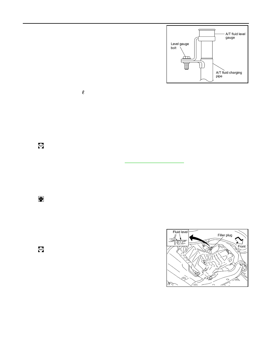
Loosen the level gauge bolt.
4.
Drain ATF from drain plug and refill with new ATF. Always refill
same volume with drained ATF.
• To replace the ATF, pour in new ATF at the A/T fluid charging
pipe with the engine idling, at the same time drain the old ATF
from the radiator cooler hose return side.
• When the color of the ATF coming out is almost same as the
color of the new ATF, the replacement is complete. The
amount of new ATF to use should be 30 to 50% increase of
the stipulated amount.
CAUTION:
• Use only Genuine NISSAN Matic J ATF. Do not mix with other ATF.
• Using ATF other than Genuine NISSAN Matic J ATF will cause deterioration in driveability and A/
T durability, and may damage the A/T, which is not covered by the warranty.
• When filling ATF, take care not to scatter heat generating parts such as exhaust.
• Do not reuse drain plug gasket.
5.
Run engine at idle speed for 5 minutes.
6.
Check A/T fluid level and condition. Refer to
. If ATF is still dirty, repeat step
2. through 5.
7.
Install the removed A/T fluid level gauge into A/T fluid charging pipe.
8.
Tighten the level gauge bolt.
Checking Transfer Fluid
INFOID:0000000001328921
Check for fluid leakage and fluid level.
CAUTION:
Never start engine while checking fluid level.
Changing Transfer Fluid
INFOID:0000000001328922
CAUTION:
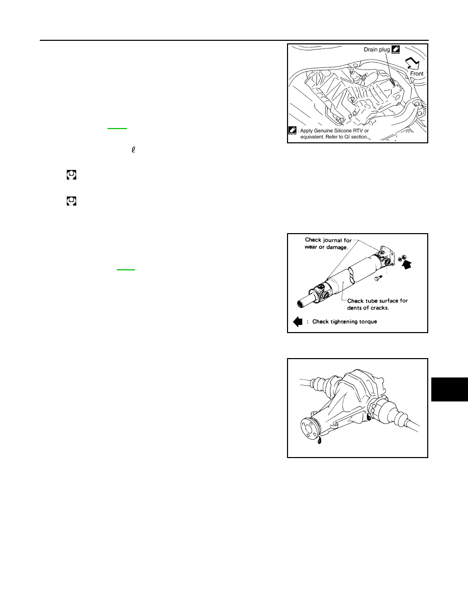
When draining fluid, protect exhaust tube flange with cover.
1.
Drain fluid from drain plug and refill with new gear fluid.
ATF: Genuine NISSAN Matic J ATF
Fluid capacity: 10.3 (10-7/8 US qt, 9-1/8 lmp qt)
Drain plug:
: 34 N·m (3.5 kg-m, 25 ft-lb)
Level gauge bolt:
: 5.1 N·m (0.52 kg-m, 45 in-lb)
SCIA4896E
Filler plug:
: 35 N·m (3.6 kg-m, 26 ft-lb)
SDIA2028E
CHASSIS AND BODY MAINTENANCE
MA-29
< SERVICE INFORMATION >
C
D
E
F
G
H
I
J
K
M
A
B
MA
N
O
P
2.
Check fluid level.
CAUTION:
Carefully fill the fluid. (Fill up for Approx. 3 minutes.)
Checking Propeller Shaft
INFOID:0000000001328923
Check propeller shaft for damage, looseness or grease leakage.
Checking Differential Gear Oil
INFOID:0000000001328924
Check for oil leakage.
Changing Differential Gear Oil
INFOID:0000000001328925
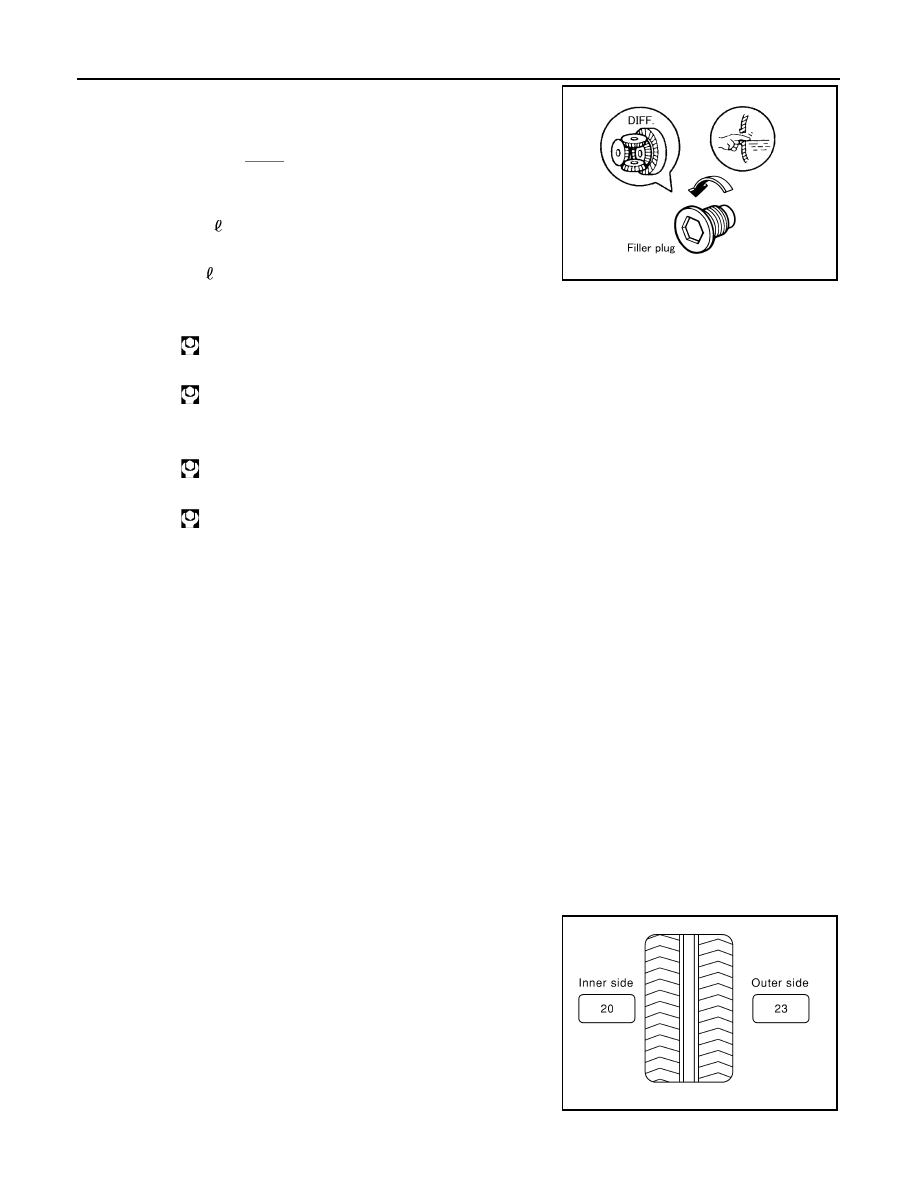
1.
Drain oil from drain plug and refill with new gear oil.
Fluid grade:
Genuine NISSAN Matic D ATF (Continental U.S. and
Alaska) or Canada NISSAN Automatic Transmis-
sion Fluid or equivalent (if available)
Refer to
Fluid capacity:
: Approx. 1.25 (2-5/8 US pt, 2-1/4 lmp pt)
Drain plug:
: 29.4 N·m (3.0 kg-m, 22 ft-lb)
Filler plug:
: 35 N·m (3.6 kg-m, 26 ft-lb)
SDIA2087E
Tightening torque:
Refer to
SMA118A
SMA012C
MA-30
< SERVICE INFORMATION >
CHASSIS AND BODY MAINTENANCE
2.
Check oil level.
Balancing Wheels (Bonding Weight Type)
INFOID:0000000001328926
REMOVAL
Using releasing agent, remove double-faced adhesive tape from the road wheel.
CAUTION:
• Be careful not to scratch the road wheel during removal.
• After removing double-faced adhesive tape, wipe clean traces of releasing agent from the road
wheel.
WHEEL BALANCE ADJUSTMENT
• If a tire balance machine has adhesion balance weight mode settings and drive-in weight mode setting,
select and adjust a drive-in weight mode suitable for road wheels.
1.
Set road wheel on tire balance machine using the center hole as a guide. Start the tire balance machine.
2.
When inner and outer unbalance values are shown on the tire balance machine indicator, multiply outer
unbalance value by 5/3 to determine balance weight that should be used. Select the outer balance weight
with a value closest to the calculated value above and install it to the designated outer position of, or at the
designated angle in relation to the road wheel.
CAUTION:
• Do not install the inner balance weight before installing the outer balance weight.
• Before installing the balance weight, be sure to clean the mating surface of the road wheel.
Indicated unbalance value
×
5/3 = balance weight to be installed
Calculation example:
23 g (0.81 oz)
×
5/3 = 38.33 g (1.35 oz)
⇒
40 g (1.41 oz) bal-
ance weight (closer to calculated balance weight value)
Note that balance weight value must be closer to the calculated
balance weight value.
Example:
37.4
⇒
35 g (1.23 oz)
37.5
⇒
40 g (1.41 oz)
Oil grade and Viscosity:
Capacity:
Front final drive (F160A)
0.65 (1 - 3/8 US pt, 1 - 1/8 lmp pt)
Rear final drive (R200)
1.4 (3 US pt, 2 - 1/2 lmp pt)
Filler plug:
Front final drive
: 34.5 N-m (3.5 kg-m, 25 ft-lb)
Rear final drive
: 34.5 N-m (3.5 kg-m, 25 ft-lb)
Drain plug:
Front final drive
: 34.5 N-m (3.5 kg-m, 25 ft-lb)
Rear final drive
: 34.5 N-m (3.5 kg-m, 25 ft-lb)
SDIA1151E
SMA054D
CHASSIS AND BODY MAINTENANCE
MA-31
< SERVICE INFORMATION >
C
D
E
F
G
H
I
J
K
M
A
B
MA
N
O
P
a.
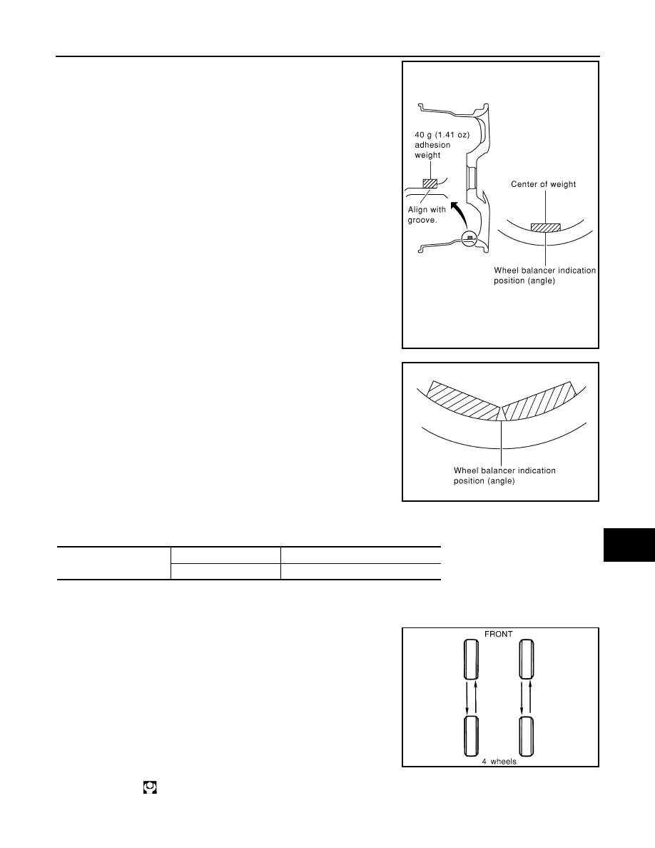
Install balance weight in the position shown in the figure at right.
b.
When installing balance weight to road wheels, set it into the
grooved area on the inner wall of the road wheel as shown in the
figure so that the balance weight center is aligned with the tire
balance machine indication position (angle).
CAUTION:
• Always use genuine NISSAN adhesion balance weights.
• Balance weights are unreusable; always replace with new
ones.
• Do not install more than three sheets of balance weight.
c.
If calculated balance weight value exceeds 50 g (1.76 oz), install
two balance weight sheets in line with each other (as shown in
the figure).
CAUTION:
Do not install one balance weight sheet on top of another.
3.
Start tire balance machine again.
4.
Install drive-in balance weight on inner side of road wheel in the
tire balance machine indication position (angle).
CAUTION:
Do not install more than two balance weights.
5.
Start tire balance machine. Make sure that inner and outer resid-
ual unbalance values are 5.0 g (0.18 oz) each or below.
• If either residual unbalance value exceeds 5.0 g (0.18 oz), repeat installation procedures.
Tire Rotation
INFOID:0000000001328927
• After rotation the tires, adjust the tire pressure.
• Retighten the wheel nuts when the vehicle has been driven for
1,000 km (600 miles) (also in cases of a flat tire, etc.).
CAUTION:
• Do not include the T-type spare tire when rotating the tires.
• When installing wheels, tighten them diagonally by dividing
the work two to three times in order to prevent the wheels
from developing any distortion.
• Be careful not to tighten wheel nut at torque exceeding the
criteria for preventing strain of disc rotor.
• Use NISSAN genuine wheel nuts for aluminum wheels.
SEIA0271E
Maximum allowable un-
balance
Dynamic (At rim flange)
Less than 5.0 g (0.18 oz) (one side)
Static (At rim flange)
Less than 20 g (0.71 oz)
SMA056D
Tightening torque of wheel nut
: 108 N·m (11 kg, 83 ft-lb)
SMA829C
Нет комментариевНе стесняйтесь поделиться с нами вашим ценным мнением.
Текст