Infiniti FX35 / FX45. Manual — part 223

BACK DOOR AUTO CLOSURE SYSTEM
BL-159
< SERVICE INFORMATION >
C
D
E
F
G
H
J
K
L
M
A
B
BL
N
O
P
Check continuity between back door opener switch terminals 1 and
2.
OK or NG
OK
>> GO TO 6.
NG
>> Replace back door opener switch.
6.
CHECK BACK DOOR CLOSURE CONTROL UNIT OUTPUT SIGNAL
1.
Connect back door closure control unit connector.
2.
Check voltage between back door closure control unit connector
D106 terminal 6 and ground.
OK or NG
OK
>> Replace Intelligent Key unit.
NG
>> Replace back door closure control unit.
Check Back Door Opener Switch (Without Intelligent Key)
INFOID:0000000001327900
1.
CHECK BACK DOOR OPENER SWITCH SIGNAL
1.
Turn ignition switch OFF.
2.
Check voltage between back door closure control unit connector and ground.
OK or NG
OK
>> Back door opener switch is OK.
NG
>> GO TO 2.
2.
CHECK HARNESS CONTINUITY
1.
Disconnect back door closure control unit and back door opener switch connector.
2.
Check continuity between back door closure control unit con-
nector D106 terminal 6 and back door opener switch connector
D112 terminal 1.
OK or NG
OK
>> GO TO 3.
NG
>> Repair or replace harness between back door closure
control unit and back door opener switch.
3.
CHECK GROUND CIRCUIT
Terminals
Condition
Continuity
1
2
Back door opener switch: ON
Yes
Back door opener switch: OFF
No
PIIA6181E
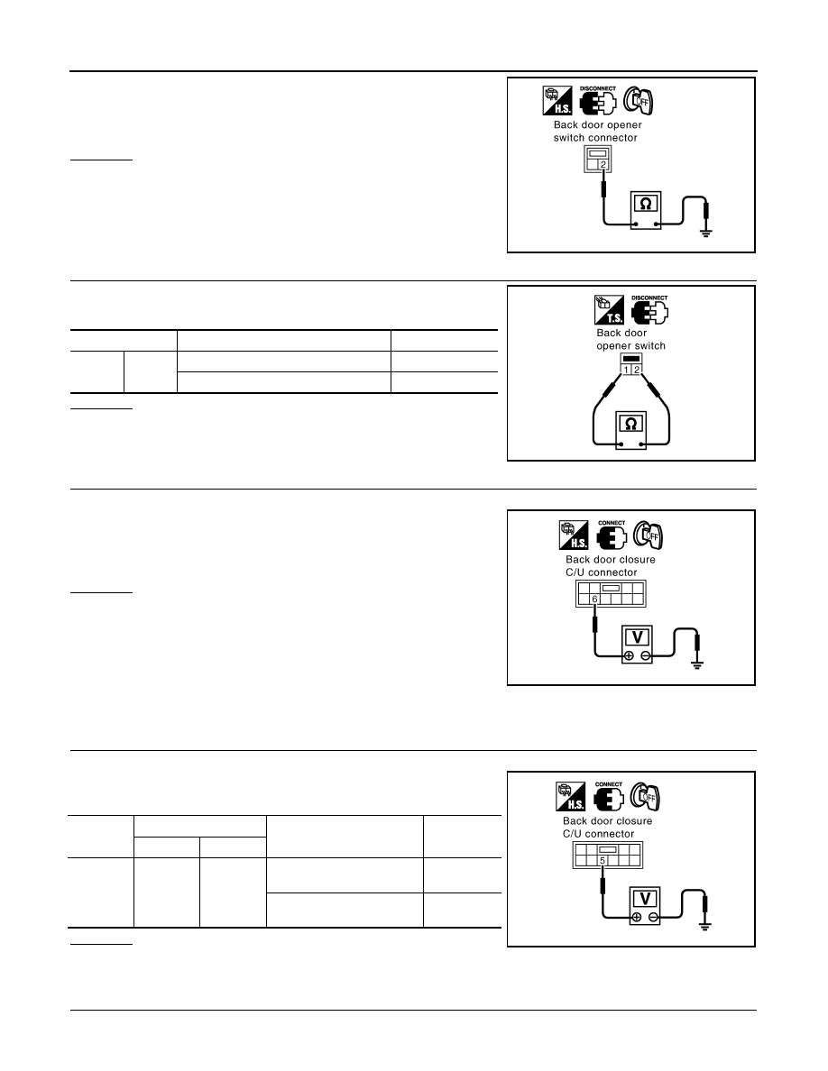
6 (LG) – Ground
: Approx. 5V
PIIA6178E
Connector
Terminals (Wire color)
Condition
Voltage (V)
(Approx.)
(+)
(-)
D106
6 (Y)
Ground
Back door opener switch
: ON
0
Back door opener switch
: OFF
5
PIIA6178E
6 (Y) – 1 (Y)
: Continuity should exist.
PIIA6179E
BL-160
< SERVICE INFORMATION >
BACK DOOR AUTO CLOSURE SYSTEM
Check continuity between back door opener switch connector D112
terminal 2 and ground.
OK or NG
OK
>> GO TO 4.
NG
>> Repair or replace harness.
4.
CHECK BACK DOOR OPENER SWITCH
Check continuity between back door opener switch terminals 1 and
2.
OK or NG
OK
>> GO TO 5.
NG
>> Replace back door opener switch.
5.
CHECK BACK DOOR CLOSURE CONTROL UNIT OUTPUT SIGNAL
1.
Connect back door closure control unit connector.
2.
Check voltage between back door closure control unit connector
D106 terminal 6 and ground.
OK or NG
OK
>> Check condition of harness and connector.
NG
>> Replace back door closure control unit.
Check Unlock Sensor (Without Intelligent Key)
INFOID:0000000001327901
1.
CHECK UNLOCK SENSOR SIGNAL
1.
Turn ignition switch OFF.
2.
Check voltage between back door closure control unit connector
and ground.
OK or NG
OK
>> Unlock sensor is OK.
NG
>> GO TO 2.
2.
CHECK HARNESS CONTINUITY
1.
Disconnect back door closure control unit and front door lock assembly (passenger side) connector.
2 (B) – Ground
: Continuity should exist.
PIIA6180E
Terminals
Condition
Continuity
1
2
Back door opener switch: ON
Yes
Back door opener switch: OFF
No
PIIA6181E
6 (Y) – Ground
: Approx. 5V
PIIA6178E
Connector
Terminals (Wire color)
Condition
Voltage (V)
(Approx.)
(+)
(-)
D106
5 (W)
Ground
Passenger side door lock is
locked
5
Passenger side door lock is
unlocked
0
PIIA6182E
BACK DOOR AUTO CLOSURE SYSTEM
BL-161
< SERVICE INFORMATION >
C
D
E
F
G
H
J
K
L
M
A
B
BL
N
O
P
2.
Check continuity between back door closure control unit con-
nector D106 terminal 5 and front door lock assembly (passenger
side) connector D40 terminal 5.
OK or NG
OK
>> GO TO 3.
NG
>> Repair or replace harness between back door closure
control unit and front door lock assembly (passenger
side).
3.
CHECK GROUND CIRCUIT
Check continuity between front door lock assembly (passenger side)
connector D40 terminal 4 and ground.
OK or NG
OK
>> GO TO 4.
NG
>> Repair or replace harness.
4.
CHECK BACK DOOR CLOSURE CONTROL UNIT OUTPUT SIGNAL
1.
Connect back door closure control unit connector.
2.
Check voltage between back door closure control unit connector
D106 terminal 5 and ground.
OK or NG
OK
>> Replace front door lock assembly (passenger side).
NG
>> Replace back door closure control unit.
Check Closure Motor
INFOID:0000000001327902
1.
CHECK BACK DOOR CLOSURE MOTOR
1.
Turn ignition switch OFF.
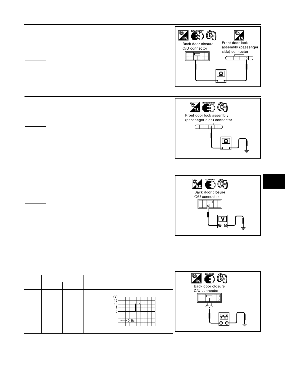
2.
Check the signal between back door closure control unit connector and ground with oscilloscope.
OK or NG
OK
>> GO TO 2.
NG
>> Replace back door closure control unit.
5 (W) – 5 (W)
: Continuity should exist.
PIIA6183E
4 (B) – Ground
: Continuity should exist.
PIIA6184E
5 (W) – Ground
: Approx. 5V
PIIA6182E
Con-
nector
Terminals (Wire color)
Back door
condition
Signal
(Reference value)
(+)
(-)
D106
2 (PU)
Ground
Fully closed
→
fully open
3 (G)
Fully open
→
fully closed
PIIA6185E
SIIA1480J

BL-162
< SERVICE INFORMATION >
BACK DOOR AUTO CLOSURE SYSTEM
2.
CHECK HARNESS CONTINUITY
1.
Disconnect back door closure control unit and back door closure motor connector.
2.
Check continuity between back door closure control unit con-
nector D106 terminals 2, 3 and back door closure motor connec-
tor D109 terminals 1, 2.
3.
Check continuity between back door closure control unit con-
nector D106 terminals 2, 3 and ground.
OK or NG
OK
>> Replace back door closure motor.
NG
>> Repair or replace harness.
Removal and Installation of Back Door Closer Control Unit
INFOID:0000000001327903
1.
Remove the back door finisher.
EI-47, "Component Parts Location"
2.
Disconnect the back door closer control unit harness, remove the screw and back door closer control unit.
2 (PU) – 1 (PU)
: Continuity should exist.
3 (G) – 2 (G)
: Continuity should exist.
2 (PU) – Ground
: Continuity should not exist.
3 (G) – Ground
: Continuity should not exist.
PIIA6186E
Нет комментариевНе стесняйтесь поделиться с нами вашим ценным мнением.
Текст