Infiniti FX35 / FX45. Manual — part 155
AV-74
< SERVICE INFORMATION >
INTEGRATED DISPLAY SYSTEM
6.
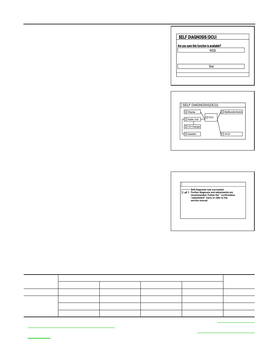
When the self-diagnosis completes, optional part confirmation
screen will be shown.
• When connection of an optional part is judged error, a screen
to check if the optional part is actually fitted on the vehicle or
not will be shown. When fitted, select the switch of the part on
the screen and press “End”. Then the “SELF DIAGNOSIS”
screen will be shown.
• When the optional part is connected normally, the switch for
the part will not appear on the screen.
7.
On the diagnosis results screen, each unit name and connection
line will be colored according to the diagnosis result, as follows.
NOTE:
• Satellite = Satellite radio tuner
• DCU = Display control unit
• Multifunction switch = A/C and AV switch
• If multiple malfunctions occur at the same time for a single
unit, the screen switch colors are determined according to the following order of priority: red > yellow >
gray.
8.
Select a switch on the diagnosis results screen, and comments
for the diagnosis results will be shown.
SELF-DIAGNOSIS RESULT
Quick Reference Table
1.
Select the applicable diagnosis number in the quick reference table of diagnosis result.
2.
Confirm the possible malfunction with the diagnosis table, and then perform inspection.
3.
Turn ignition switch OFF and perform self-diagnosis again.
• When A/C and AV switch has a malfunction, the self-diagnosis cannot be started. Refer to
Operate System with A/C and AV Switch"
.
• When display has a malfunction, the self-diagnosis cannot be started. Refer to
Self-Diagnosis Codes
SKIB8673E
Green
: No malfunctioning.
Gray
: Cannot be judged by self-diagnosis results.
Red
: Unit is malfunctioning.
SKIB7872E
SKIA4211E
Switch color
Screen switch
Diagnosis No.
DCU
Display
Audio Unit
Satellite
Red
×
1
Gray
×
2
×
×
3
×
4
INTEGRATED DISPLAY SYSTEM
AV-75
< SERVICE INFORMATION >
C
D
E
F
G
H
I
J
L
M
A
B
AV
N
O
P
Confirmation/Adjustment Mode
INFOID:0000000001328724
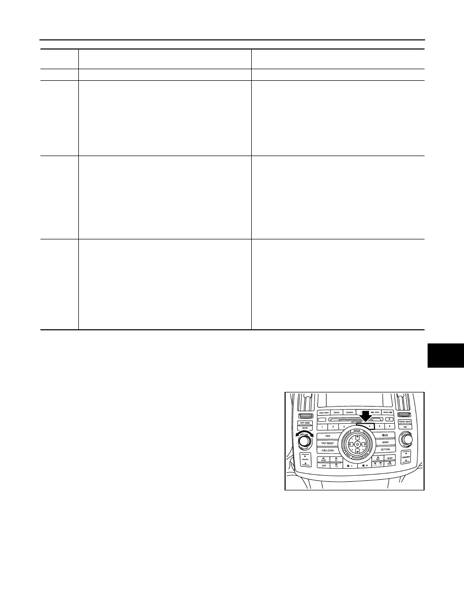
OPERATION PROCEDURE
1.
Start the engine.
2.
Turn the audio system OFF.
3.
While pressing the “4” button, turn the volume control dial clock-
wise or counterclockwise for 30 clicks or more. (When the self-
diagnosis mode is started, a short beep will be heard.)
• Shifting from current screen to previous screen is performed
by pressing “BACK” button.
Diagnosis
No.
Possible cause
Action to take
1
Display control unit malfunction is detected.
Replace display control unit.
2
Malfunction is detected on communication signal between
display control unit and display.
1.
Check communication circuit between display control
unit and display.
2.
Check communication signal between display control
unit and display.
3.
If the results from the above checkup show no mal-
function, replace either display control unit or display,
and then start self-diagnosis.
4.
If self-diagnosis results still show any malfunction, re-
place the other unit.
3
• Audio unit power supply circuit malfunction is detected.
• Malfunction is detected on communication signal be-
tween display control unit and audio unit.
1.
Check audio unit power supply circuit.
2.
Check communication circuit between display control
unit and audio unit.
3.
Check communication signal between display control
unit and audio unit.
4.
If the results from the above checkup show no mal-
function, replace either display control unit or audio
unit, and then start self-diagnosis.
5.
If self-diagnosis results still show any malfunction, re-
place the other unit.
4
• Satellite radio tuner power supply and ground circuit mal-
function is detected.
• Malfunction is detected on communication signal be-
tween audio unit and satellite radio tuner.
1.
Check satellite radio tuner power supply and ground
circuit.
2.
Check communication circuit between audio unit and
satellite radio tuner.
3.
Check communication signal between audio unit and
satellite radio tuner.
4.
If the results from the above checkup show no mal-
function, replace either audio unit or satellite radio tun-
er, and then start self-diagnosis.
5.
If self-diagnosis results still show any malfunction, re-
place the other unit.
SKIB8743E
AV-76
< SERVICE INFORMATION >
INTEGRATED DISPLAY SYSTEM
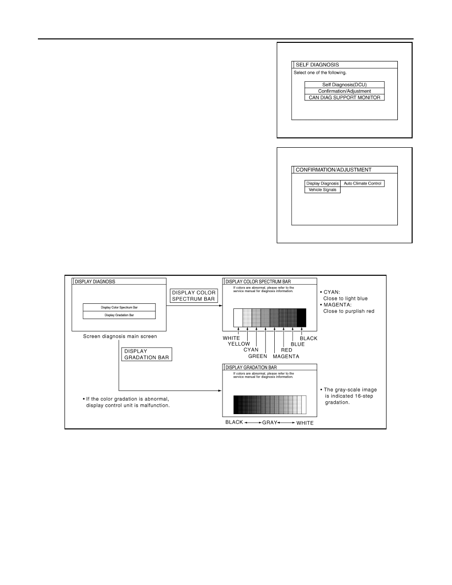
4.
The initial trouble diagnosis screen will be shown, and items
“Self Diagnosis (DCU)”, “Confirmation/Adjustment” and “CAN
DIAG SUPPORT MONITOR” will become selective.
5.
Select “Confirmation/Adjustment”.
6.
Each diagnosis is shown by selecting each screen switch on
Confirmation/Adjustment screen.
DISPLAY DIAGNOSIS
Color tone and shading of the display control unit-generated image can be checked by the display of a color
bar and a gray scale.
• If RGB signal is malfunctioning, the tint of the color bar display is as follows.
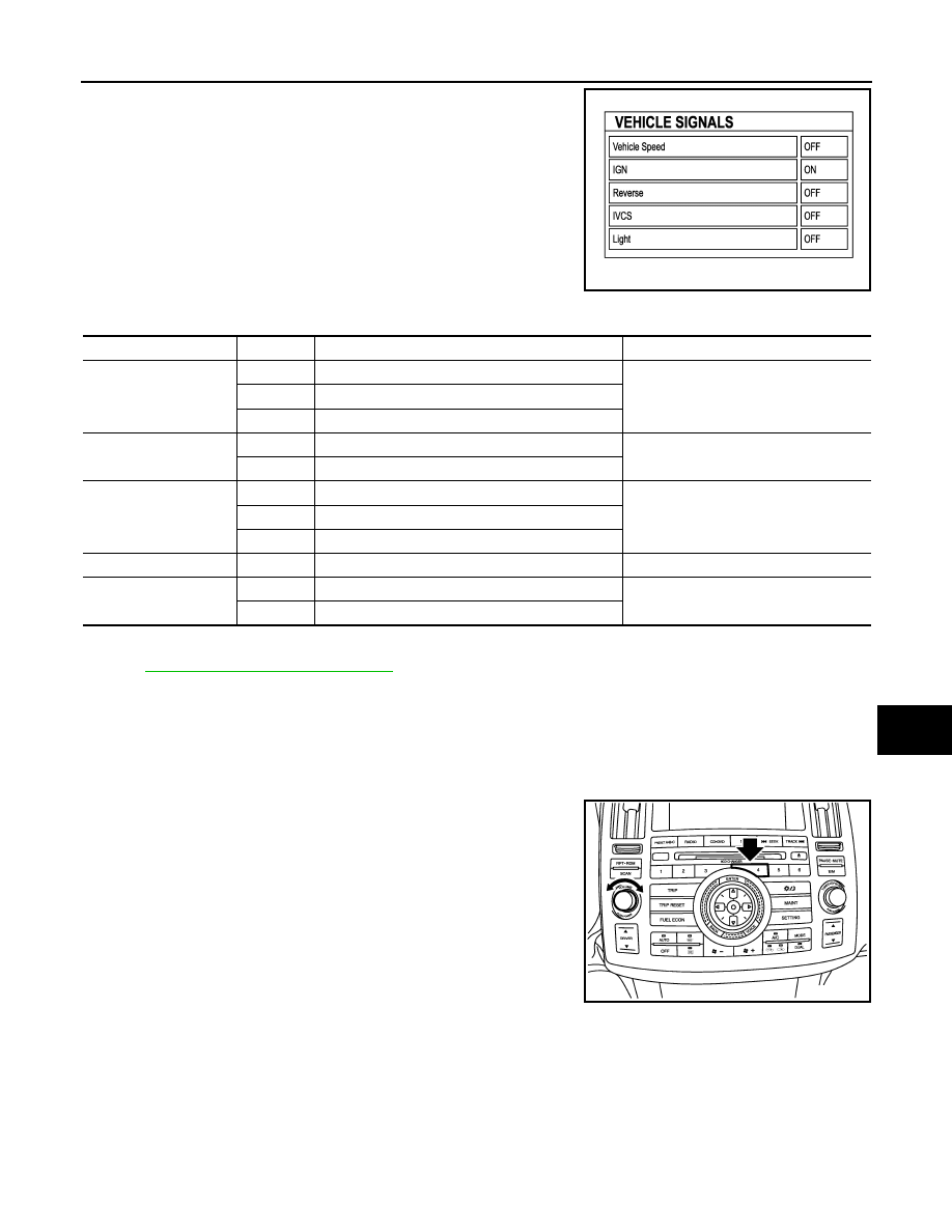
VEHICLE SIGNALS
SKIB7871E
SKIB7873E
R (red) signal error
: Light blue (Cyan) tint
G (green) signal error
: Purple (Magenta) tint
B (blue) signal error
: Yellow tint
SKIB7777E
INTEGRATED DISPLAY SYSTEM
AV-77
< SERVICE INFORMATION >
C
D
E
F
G
H
I
J
L
M
A
B
AV
N
O
P
A comparison check can be made of each actual vehicle signal and
the signals recognized by the display control unit.
NOTE:
In case of confirming light signal, set the following D/N mode to ON/
OFF of lighting switch (normal setting).
• OFF: D (Day mode)
• ON: N (Night mode)
Unless above setting, light signal (ON/OFF) may not be accurately
displayed.
AUTO CLIMATE CONTROL
ATC-43, "Self-Diagnosis Function"
CAN Diagnostic Support Monitor
INFOID:0000000001328725
OPERATION PROCEDURE
1.
Start the engine.
2.
Turn the audio system OFF.
3.
While pressing the “4” button, turn the volume control dial clock-
wise or counterclockwise for 30 clicks or more. (When the self-
diagnosis mode is started, a short beep will be heard.)
• Shifting from current screen to previous screen is performed
by pressing “BACK” button.
SKIB7778E
Diagnosis item
Display
Condition
Remarks
Vehicle Speed
ON
When vehicle speed is more than 0 km/h (0 MPH)
Changes in indication may be delayed.
This is normal.
OFF
When vehicle speed is 0 km/h (0 MPH)
—
Ignition switch in ACC position
IGN
ON
Ignition switch ON
—
OFF
Ignition switch ACC position
Reverse
ON
Selector lever in R position
Changes in indication may be delayed.
This is normal.
OFF
Selector lever in any position other than R position
—
Ignition switch in ACC position
IVCS
OFF
—
This vehicle does not use it.
Light
ON
Lighting switch ON
—
OFF
Lighting switch OFF
SKIB8743E
Нет комментариевНе стесняйтесь поделиться с нами вашим ценным мнением.
Текст