Infiniti FX35 / FX45. Manual — part 282

DTC INDEX
DI-3
< SERVICE INFORMATION >
C
D
E
F
G
H
I
J
L
M
A
B
DI
N
O
P
SERVICE INFORMATION
DTC INDEX
U1000 - U1010
INFOID:0000000001422603
B2202 - B2205
INFOID:0000000001422604
C1B00 - C1B03
INFOID:0000000001422605
DTC
Items (CONSULT screen terms)
Reference
U1000
CAN COMM CIRCUIT
DI-30, "DTC [U1000] CAN Communication Circuit"
U1010
CONTROL UNIT (CAN)
DI-86, "DTC [U1010] CONTROL UNIT (CAN)"
DTC
Items (CONSULT screen terms)
Reference
B2202
METER COMM CIRC
DI-30, "DTC [B2202] Meter Communication Circuit"
B2205
VEHICLE SPEED CIRC
DI-32, "DTC [B2205] Vehicle Speed Circuit"
DTC
Items (CONSULT screen terms)
Reference
C1B00
CAMERA UNIT MALF
DI-85, "DTC [C1B00] CAMERA UNIT MALF"
C1B01
CAM AIMING INCMP
DI-85, "DTC [C1B01] CAM AIMING INCMP"
C1B02
VHCL SPD DATA MALF
DI-85, "DTC [C1B02] VHCL SPD DATA MALF"
C1B03
ABNRML TEMP DETECT
DI-4
< SERVICE INFORMATION >
PRECAUTION
PRECAUTION
Precaution for Supplemental Restraint System (SRS) "AIR BAG" and "SEAT BELT
PRE-TENSIONER"
INFOID:0000000001612921
The Supplemental Restraint System such as “AIR BAG” and “SEAT BELT PRE-TENSIONER”, used along
with a front seat belt, helps to reduce the risk or severity of injury to the driver and front passenger for certain
types of collision. This system includes seat belt switch inputs and dual stage front air bag modules. The SRS
system uses the seat belt switches to determine the front air bag deployment, and may only deploy one front
air bag, depending on the severity of a collision and whether the front occupants are belted or unbelted.
Information necessary to service the system safely is included in the “SUPPLEMENTAL RESTRAINT SYS-
TEM” and “SEAT BELTS” of this Service Manual.
WARNING:
• To avoid rendering the SRS inoperative, which could increase the risk of personal injury or death in
the event of a collision which would result in air bag inflation, all maintenance must be performed by
an authorized NISSAN/INFINITI dealer.
• Improper maintenance, including incorrect removal and installation of the SRS, can lead to personal
injury caused by unintentional activation of the system. For removal of Spiral Cable and Air Bag
Module, see the “SUPPLEMENTAL RESTRAINT SYSTEM”.
• Do not use electrical test equipment on any circuit related to the SRS unless instructed to in this
Service Manual. SRS wiring harnesses can be identified by yellow and/or orange harnesses or har-
ness connectors.
COMBINATION METERS
DI-5
< SERVICE INFORMATION >
C
D
E
F
G
H
I
J
L
M
A
B
DI
N
O
P
COMBINATION METERS
System Description
INFOID:0000000001328433
UNIFIED METER CONTROL UNIT
• Speedometer, odo/trip meter, tachometer, fuel gauge and water temperature gauge are controlled by the
unified meter control unit, which is built into the combination meter. Unified meter control unit receives sig-
nals from unified meter and A/C amp.
• Warning lamp and indicator lamp of combination meter are controlled by signals drawn from the unified
meter and A/C amp.
• Odo/trip meter, A/T indicator and ICC system display segments can be checked in self-diagnosis mode.
• Meters/gauges can be checked in self-diagnosis mode.
UNIFIED METER AND A/C AMP.
in “UNIFIED METER AND A/C AMP”.
POWER SUPPLY AND GROUND CIRCUIT
Power is supplied at all times
• through 10A fuse [No. 19, located in the fuse block (J/B)]
• to combination meter terminal 8, and
• to unified meter and A/C amp. terminal 21.
With the ignition switch in the ON or START position, power is supplied
• through 10A fuse [No. 14, located in the fuse block (J/B)]
• to combination meter terminal 7,
• through 10A fuse [No. 12, located in the fuse block (J/B)]
• to unified meter and A/C amp. terminal 22.
With the ignition switch in the ACC or ON position, power is supplied
• through 10A fuse [No. 6, located in the fuse block (J/B)]
• to combination meter terminal 4,
• through 15A fuse [No. 10, located in the fuse block (J/B)], and
• through 15A fuse [No. 11, located in the fuse block (J/B)]
• to unified meter and A/C amp. terminal 46.
Ground is supplied
• to combination meter terminals 5, 6 and 15
• through grounds M35, M45 and M85,
• to unified meter and A/C amp. terminals 29 and 30
• through grounds M35, M45 and M85.
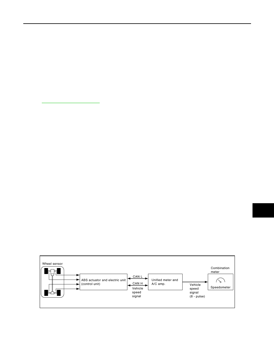
SPEEDOMETER
The speedometer indicates the vehicle speed.
• ABS actuator and electric unit (control unit) provides a vehicle speed signal to the unified meter and A/C
amp. with CAN communication.
• Unified meter and A/C amp. converts the vehicle speed signal to the 8-pulse signal, and outputs the vehicle
speed signal (8-pulse) to combination meter.
• Combination meter indicates the vehicle speed according to vehicle speed signal (8-pulse) signal.
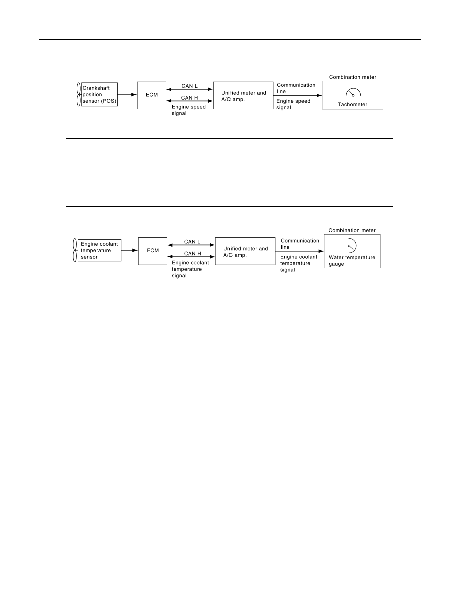
TACHOMETER
The tachometer indicates engine speed in revolutions per minute (rpm).
• ECM provides engine speed signal to unified meter and A/C amp. with CAN communication.
• Unified meter and A/C amp. transmits engine speed signal to combination meter with communication line.
SKIB7332E
DI-6
< SERVICE INFORMATION >
COMBINATION METERS
• Combination meter indicates the engine speed according to engine speed signal.
WATER TEMPERATURE GAUGE
The water temperature gauge indicates the engine coolant temperature.
• ECM provides engine coolant temperature signal to unified meter and A/C amp. with CAN communication.
• Unified meter and A/C amp. transmits engine coolant temperature signal to combination meter with commu-
nication line.
• Combination meter indicates the engine coolant temperature according to engine coolant temperature sig-
nal.
FUEL GAUGE
The fuel gauge indicates the approximate fuel level in the fuel tank.
• Unified meter and A/C amp. reads a resistor signal from fuel level sensor.
Signal is supplied
- from unified meter and A/C amp. terminal 36
- through the fuel level sensor unit and fuel pump (main) terminals 5 and 2, and
- through the fuel level sensor unit (sub) terminals 2 and 1
- to unified meter and A/C amp. terminal 28 for the fuel gauge.
• Unified meter and A/C amp. provides a fuel level signal to combination meter with communication line.
• Combination meter indicates the approximate fuel level according to the fuel level signal.
ODO/TRIP METER
• ABS actuator and electric unit (control unit) provides a vehicle speed signal to the unified meter and A/C
amp. with CAN communication.
• Unified meter and A/C amp. converts the vehicle speed signal to the 8-pulse signal, and outputs the vehicle
speed signal (8-pulse) to combination meter.
• Combination meter uses the vehicle speed signal (8-pulse) to calculate the mileage, and displays it.
How to Change The Display For Odo/trip Meter
PKIB7631E
PKIB7632E
Нет комментариевНе стесняйтесь поделиться с нами вашим ценным мнением.
Текст