Infiniti FX35 / FX45. Manual — part 679
CYLINDER HEAD
EM-233
< SERVICE INFORMATION >
[VK45DE]
C
D
E
F
G
H
I
J
K
L
M
A
EM
N
P
O
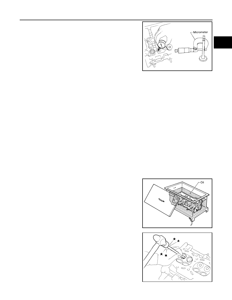
Measure the diameter of valve stem with micrometer.
Valve Guide Inner Diameter
Measure the inner diameter of valve guide with inside micrometer.
Valve Guide Clearance
(Valve guide clearance) = (Valve guide inner diameter) – (Valve stem diameter).
• If the calculated value exceeds the limit, replace valve and/or valve guide. When valve guide must be
replaced, refer to "VALVE GUIDE REPLACEMENT".
VALVE GUIDE REPLACEMENT
When valve guide is removed, replace with oversized [0.2 mm (0.008 in)] valve guide.
1.
To remove valve guide, heat cylinder head to 110 to 130
°
C (230
to 266
°
F) by soaking in heated oil.
2.
Drive out valve guide with a press [under a 20 kN (2 ton, 2.2 US
ton, 2.0 lmp ton) pressure] or hammer and valve guide drift
(commercial service tool).
CAUTION:
Cylinder head contains heat. When working, wear protec-
tive equipment to avoid getting burned.
Standard
Intake
: 5.972 - 5.980 mm (0.2351 - 0.2354 in)
Exhaust
: 5.962 - 5.970 mm (0.2347 - 0.2350 in)
SEM938C
Standard
Intake and Exhaust
: 6.000 - 6.018 mm (0.2362 - 0.2369 in)
Valve guide clearance:
Standard
Intake
: 0.020 - 0.046 mm (0.0008 - 0.0018 in)
Exhaust
: 0.030 - 0.056 mm (0.0012 - 0.0022 in)
Limit
Intake
: 0.08 mm (0.0031 in)
Exhaust
: 0.1 mm (0.004 in)
SEM008A
SEM931C
EM-234
< SERVICE INFORMATION >
[VK45DE]
CYLINDER HEAD
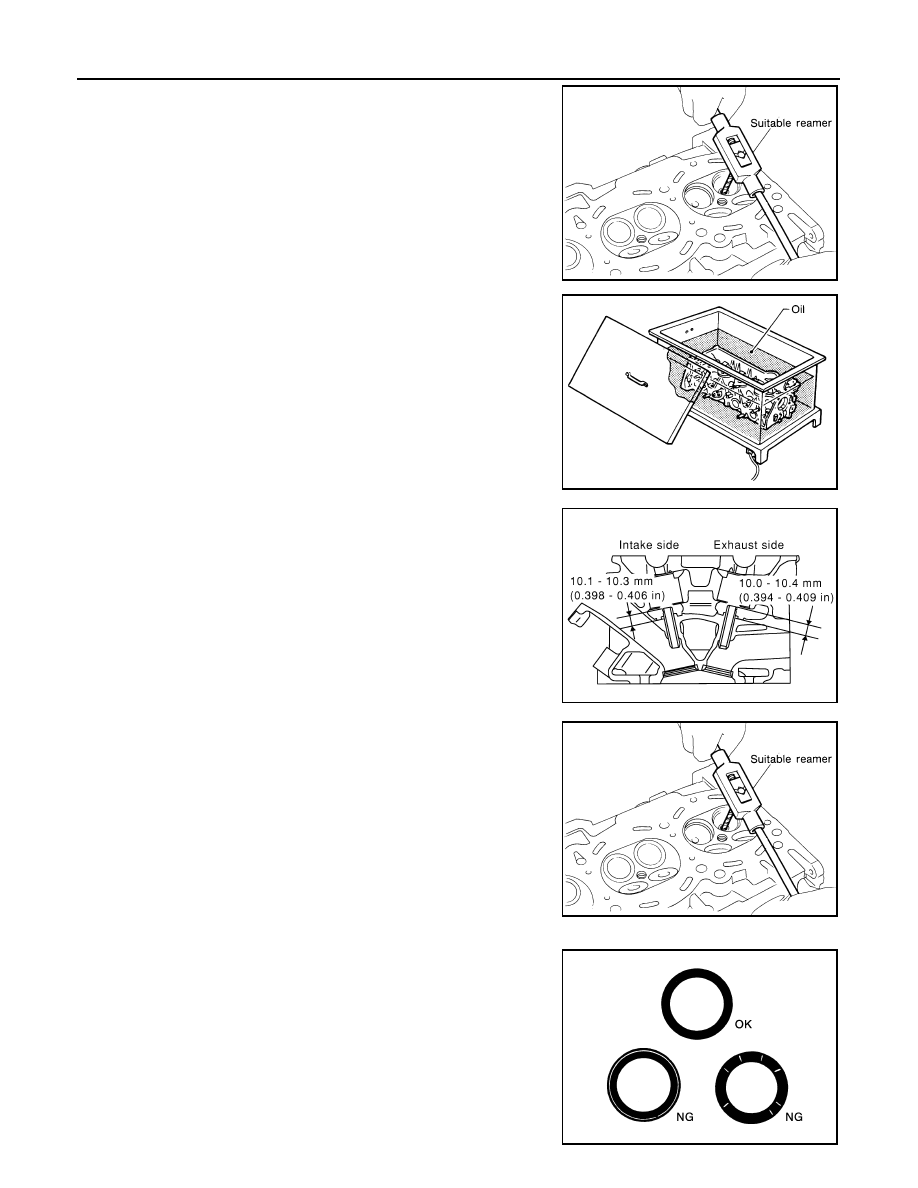
3.
Using valve guide reamer (commercial service tool), ream cylin-
der head valve guide hole.
4.
Heat cylinder head to 110 to 130
°
C (230 to 266
°
F) by soaking in
heated oil.
5.
Using valve guide drift (commercial service tool), press valve
guide from camshaft side to the dimensions as in the figure.
CAUTION:
Cylinder head contains heat. When working, wear protec-
tive equipment to avoid getting burned.
6.
Using valve guide reamer (commercial service tool), apply
reamer finish to valve guide.
VALVE SEAT CONTACT
• After confirming that the dimensions of valve guides and valves are
within the specifications, perform this procedure.
• Apply prussian blue (or white lead) onto contacting surface of valve
seat to check the condition of the valve contact on the surface.
• Check if the contact area band is continuous all around the circum-
ference.
• If not, grind to adjust valve fitting and check again. If the contacting
surface still has “NG” conditions even after the re-check, replace
valve seat. Refer to "VALVE SEAT REPLACEMENT".
Valve guide hole diameter (for service parts):
Intake and exhaust
: 10.175 - 10.196 mm (0.4006 - 0.4014 in)
SEM932C
SEM008A
PBIC0078E
Standard:
Intake and exhaust
: 6.000 - 6.018 mm (0.2362 - 0.2369 in)
SEM932C
SBIA0322E
CYLINDER HEAD
EM-235
< SERVICE INFORMATION >
[VK45DE]
C
D
E
F
G
H
I
J
K
L
M
A
EM
N
P
O
VALVE SEAT REPLACEMENT
When valve seat is removed, replace with oversized [0.5 mm (0.020 in)] valve seat.
1.
Bore out old seat until it collapses. Boring should not continue beyond the bottom face of the seat recess
in cylinder head. Set the machine depth stop to ensure this. Refer to
CAUTION:
Prevent to scratch cylinder head by excessive boring.
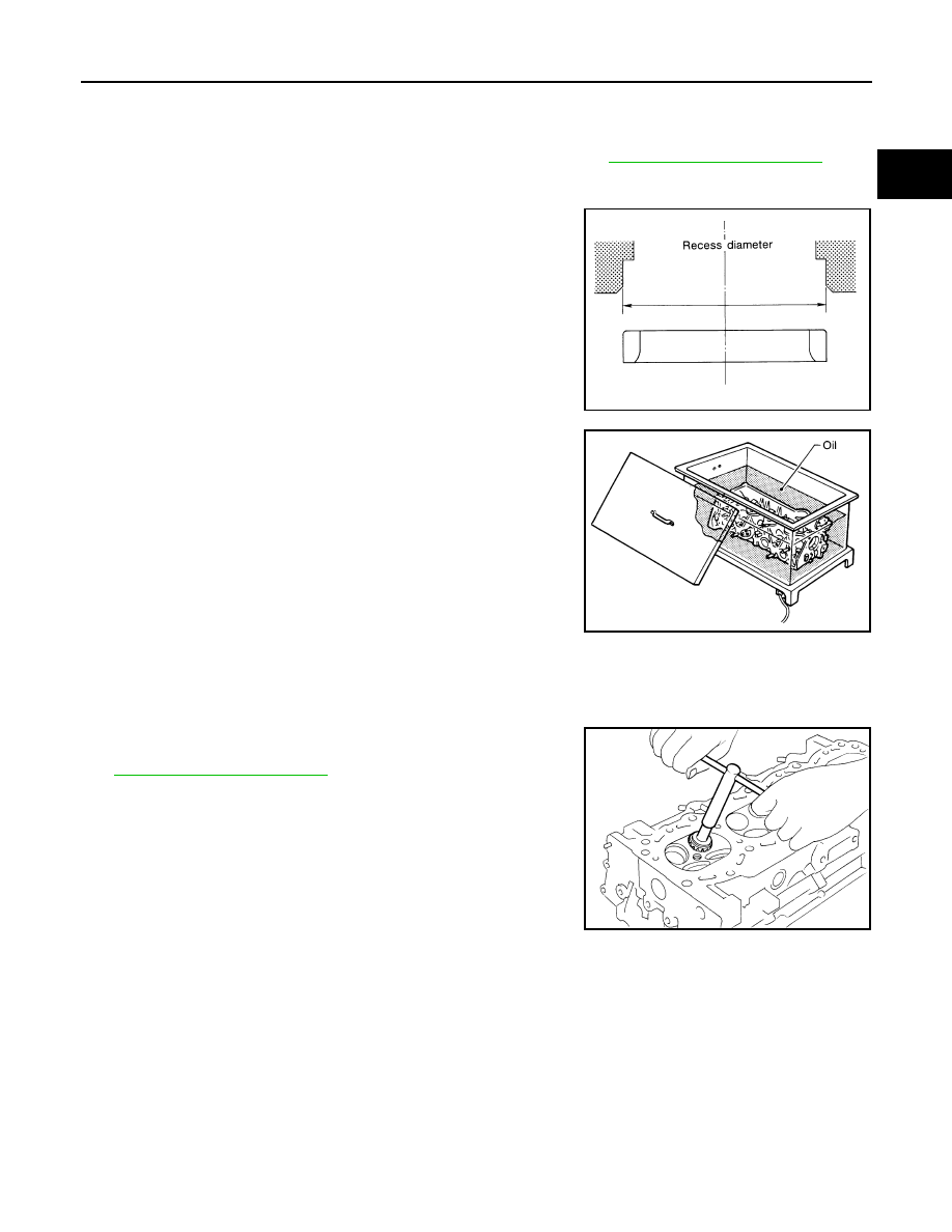
2.
Ream cylinder head recess diameter for service valve seat.
• Be sure to ream in circles concentric to valve guide center.
This will enable valve to fit correctly.
3.
Heat cylinder head to 110 to 130
°
C (230 to 266
°
F) by soaking in
heated oil.
4.
Provide valve seats cooled well with dry ice. Force fit valve seat into cylinder head.
CAUTION:
• Avoid directly touching cold valve seats.
• Cylinder head contains heat. When working, wear protective equipment to avoid getting burned.
5.
Using valve seat cutter set (commercial service tool) or valve
seat grinder, finish seat to the specified dimensions. Refer to
CAUTION:
When using valve seat cutter, firmly grip cutter handle with
both hands. Then, press on the contacting surface all
around the circumference to cut in a single drive. Improper
pressure on with cutter or cutting many different times may
result in stage valve seat.
6.
Using compound, grind to adjust valve fitting.
7.
Check again for normal contact. Refer to "VALVE SEAT CONTACT".
VALVE SPRING SQUARENESS
Oversize (Service) [0.5 mm (0.020 in)]
Intake
: 37.500 - 37.516 mm (1.4764 - 1.4770 in)
Exhaust
: 32.700 - 32.716 mm (1.2874 - 1.2880 in)
SEM795A
SEM008A
SEM934C
EM-236
< SERVICE INFORMATION >
[VK45DE]
CYLINDER HEAD
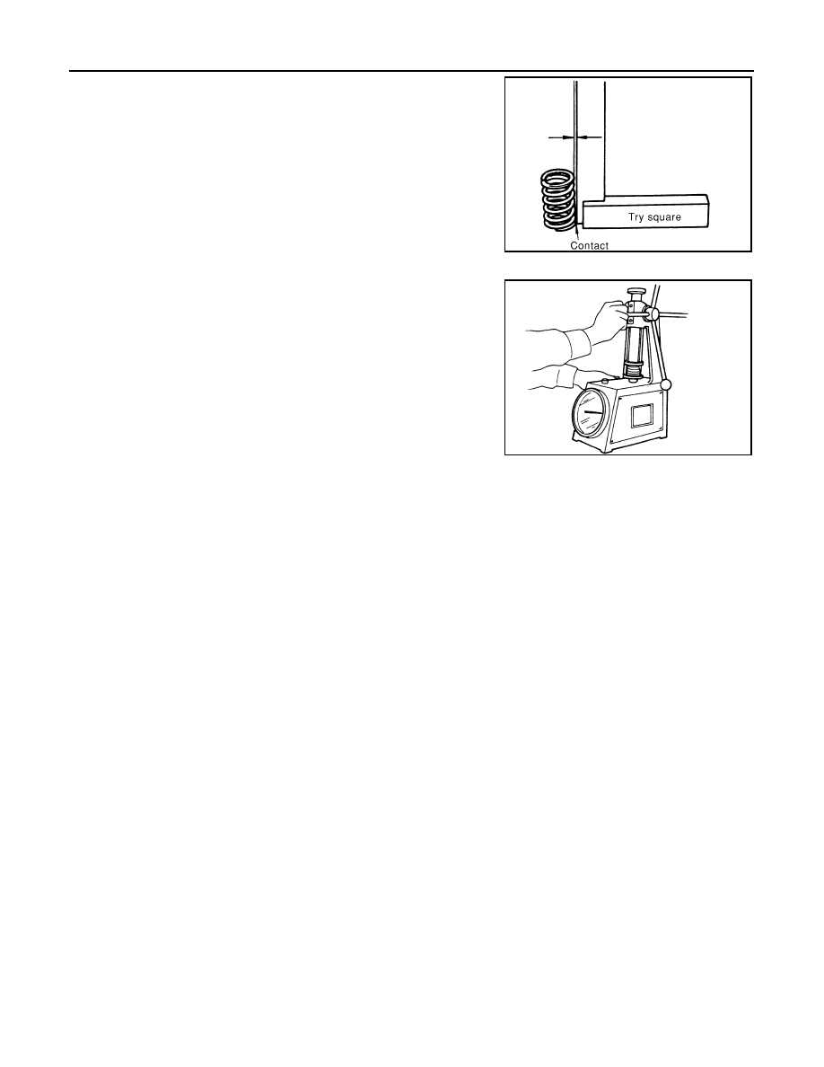
• Set try square along the side of valve spring and rotate spring.
Measure the maximum clearance between the top face of spring
and try square.
• If it exceeds the limit, replace valve spring.
VALVE SPRING DIMENSIONS AND VALVE SPRING PRESSURE LOAD
• Check valve spring pressure at the specified spring height.
• If the installation load or load with valve open is out of the standard, replace valve spring.
Limit
: 2.0 mm (0.079 in)
PBIC0080E
Standard:
Intake and exhaust
Free height
: 46.35 - 46.85 mm (1.8248 - 1.8445 in)
Installation height
: 33.8 mm (1.331 in)
Installation load
: 165 - 189 N (16.8 - 19.3 kg, 37 - 42 lb)
Height during valve open
: 24.4 mm (0.961 in)
Load with valve open
: 290 - 330 N (29.6 - 33.7 kg, 65 - 74 lb)
SEM113
Нет комментариевНе стесняйтесь поделиться с нами вашим ценным мнением.
Текст