Infiniti FX35 / FX45. Manual — part 680
ENGINE ASSEMBLY
EM-237
< SERVICE INFORMATION >
[VK45DE]
C
D
E
F
G
H
I
J
K
L
M
A
EM
N
P
O
ENGINE ASSEMBLY
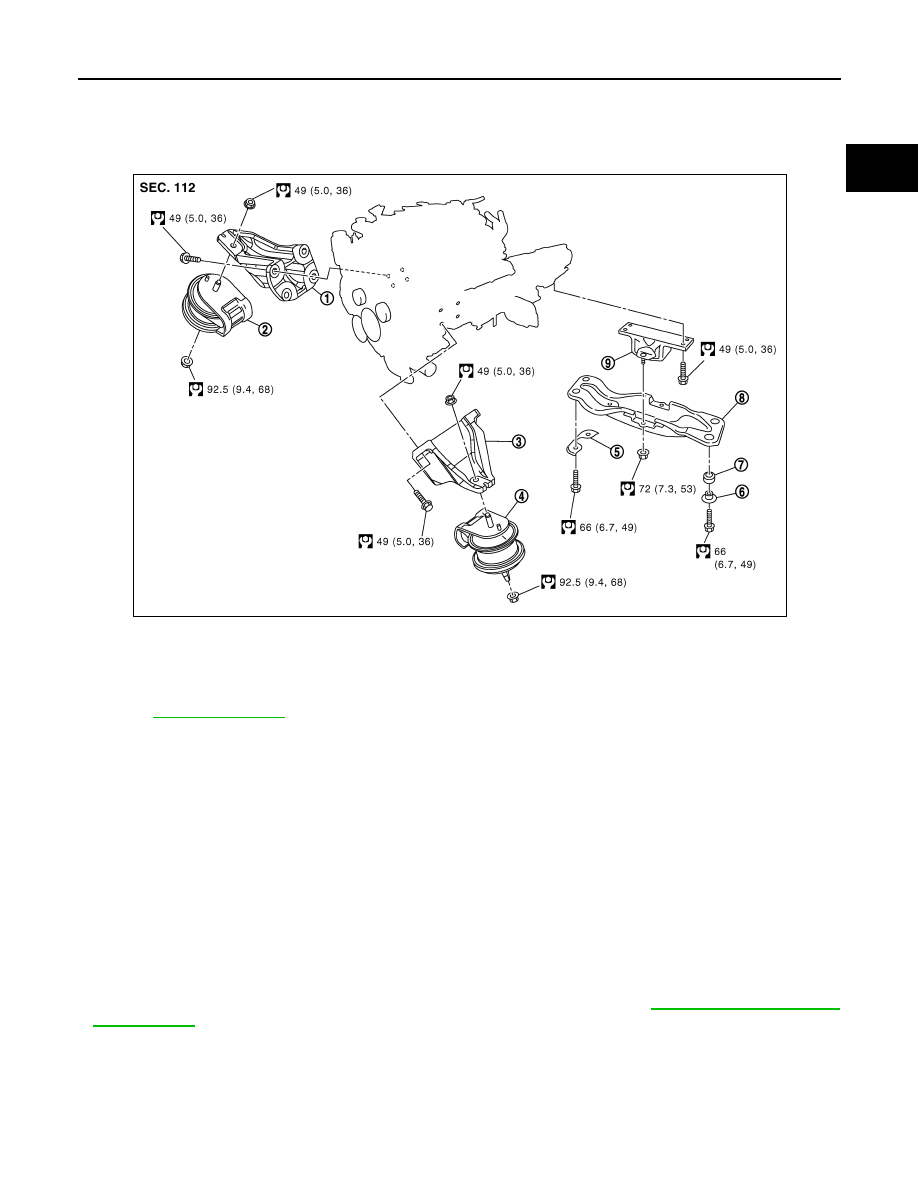
Component
INFOID:0000000001325801
• Refer to
Removal and Installation
INFOID:0000000001325802
WARNING:
• Situate vehicle on a flat and solid surface.
• Place chocks at front and back of rear wheels.
• For engines not equipped with engine slingers, attach proper slingers and bolts described in PARTS
CATALOG.
CAUTION:
• Always be careful to work safely, avoid forceful or uninstructed operations.
• Do not start working until exhaust system and engine coolant are cool enough.
• If items or work required are not covered by the engine section, refer to the applicable sections.
• Always use the support point specified for lifting.
• Use either 2-pole lift type or separate type lift as best you can. If board-on type is used for unavoid-
able reasons, support at the rear axle jacking point with transmission jack or similar tool before
starting work, in preparation for the backward shift of center of gravity.
• For supporting points for lifting and jacking point at rear axle, refer to
REMOVAL
Outline
At first, remove engine, transmission assembly and front final drive with front suspension member from vehicle
downward. Then separate engine from transmission.
Preparation
1.
Engine mounting bracket (RH)
2.
Engine mounting insulator (RH)
3.
Engine mounting bracket (LH)
4.
Engine mounting insulator (LH)
5.
Plate
6.
Collar
7.
Grommet
8.
Engine rear member
9.
Engine mounting insulator (rear)
JPBIA0902GB

EM-238
< SERVICE INFORMATION >
[VK45DE]
ENGINE ASSEMBLY
1.
Release fuel pressure. Refer to
.
2.
Drain engine coolant from radiator. Refer to
CO-37, "Changing Engine Coolant"
.
CAUTION:
• Perform this step when engine is cold.
• Do not spill engine coolant on drive belts.
3.
Disconnect both battery terminal. Refer to
4.
Remove crankshaft position sensor (POS) from transmission.
CAUTION:
• Handle carefully to avoid dropping and shocks.
• Do not disassemble.
• Do not allow metal powder to adhere to magnetic part at sensor tip.
• Do not place sensors in a location where they are exposed to magnetism.
5.
Remove the following parts:
• Hood assembly: Refer to
.
• Engine cover: Refer to
.
• Front and rear engine undercover
• Air duct (inlet), air duct and air cleaner case assembly: Refer to
.
• Drive belts: Refer to
• Radiator and radiator hoses (upper and lower): Refer to
.
• Front road wheels and tires
Engine Room LH
1.
Disconnect engine room harness from the engine side and set it aside for easier work.
2.
Disconnect heater hoses, and install plugs to avoid leakage of engine coolant.
3.
Disconnect ground cable from exhaust manifold cover to vehicle.
4.
Disconnect vacuum hose between vehicle and engine and set it aside.
5.
Discharge refrigerant from A/C circuit. Refer to
ATC-120, "HFC-134a (R-134a) Service Procedure"
6.
Remove A/C piping from A/C compressor, and temporarily fasten it on vehicle with a rope. Refer to
.
Engine Room RH
1.
Disconnect fuel feed hose and EVAP hose. Refer to
CAUTION:
Fit plugs onto disconnected hose to prevent fuel leak.
2.
Disconnect engine room harness from the engine side and set it aside for easier work.
3.
Disconnect ground cable from exhaust manifold cover to vehicle.
4.
Disconnect vacuum hose between vehicle and engine and set it aside.
5.
Disconnect reservoir tank of power steering oil pump from engine, and move it aside for easier work.
CAUTION:
When temporarily securing, keep reservoir tank upright to avoid a fluid leak.
Vehicle Underbody
1.
Remove front cross bar. Refer to
FSU-5, "On-Vehicle Inspection and Service"
.
2.
Disconnect power steering oil pump from engine. Move it from its location and secure with a rope for eas-
ier work. Refer to
PS-29, "Removal and Installation (VK45DE Models)"
.
3.
Remove A/T fluid cooler tube. Refer to
AT-241, "Removal and Installation (2WD Models)"
.
4.
Remove exhaust front tube and center muffler with power tool. Refer to
5.
Remove RH and LH transverse link mounting bolts and nuts. Refer to
FSU-13, "Removal and Installation"
.
6.
Disconnect stabilizer connecting rod lower. Refer to
FSU-5, "On-Vehicle Inspection and Service"
.
7.
Remove A/T control rod at control device assembly side. Then temporarily secure it on transmission, so
that it does not sag. Refer to
AT-205, "Control Device Removal and Installation"
8.
Remove rear plate cover from oil pan. Then remove bolts fixing drive plate to torque converter. Refer to
AT-241, "Removal and Installation (2WD Models)"
9.
Remove transmission joint bolts which pierce at oil pan lower rear side. Refer to
.

ENGINE ASSEMBLY
EM-239
< SERVICE INFORMATION >
[VK45DE]
C
D
E
F
G
H
I
J
K
L
M
A
EM
N
P
O
10. Disconnect steering lower joint at power steering gear assembly side, and release steering lower shaft.
PS-12, "Removal and Installation"
.
11. Remove rear propeller shaft. Refer to
• After disconnection, plug the opening on transmission side.
12. Remove front drive shaft (both side). Refer to
FAX-13, "On-Vehicle Inspection"
.
13. Remove front propeller shaft. Refer to
.
14. Remove three way catalyst (both bank). Refer to
Removal Work
1.
Install engine slingers into front of cylinder head (left bank) and
front of cylinder head (right bank).
2.
Lift with hoist and secure engine in position.
3.
Use manual lift table caddy (commercial service tool) or equivalently rigid tool such as transmission jack.
Securely support bottom of suspension member and transmission.
CAUTION:
Put a piece of wood or something similar as the supporting surface, secure a completely stable
condition.
4.
Remove engine rear member mounting bolts.
5.
Remove front suspension member mounting nuts with power tool. Refer to
.
6.
Carefully lower jack, or raise lift to remove engine, transmission
front final drive and front suspension member assembly. When
performing work, observe the following caution:
CAUTION:
• Confirm there is no interference with vehicle.
• Make sure that all connection points have been discon-
nected.
• Keep in mind the center of vehicle gravity changes. If nec-
essary, use jack(s) to support vehicle at rear jacking
point(s) to prevent it from falling it off the lift.
Separation Work
1.
Change engine slinger installing to cylinder head (right bank).
NOTE:
In order to keep secure position when hoisting engine.
2.
Remove engine mounting insulators (RH and LH) under side nut with power tool.
3.
Lift with hoist and separate engine and transmission assembly from front suspension member.
CAUTION:
• Before and during this lifting, always make sure that any harnesses are left connected.
Slinger bolts:
: 33.4 N·m (3.4 kg-m, 25 ft-lb)
PBIC1556E
PBIC1557E
Slinger bolts:
: 33.4 N·m (3.4 kg-m, 25 ft-lb)
PBIC2447E
EM-240
< SERVICE INFORMATION >
[VK45DE]
ENGINE ASSEMBLY
• Avoid damage to and oil/grease smearing or spills onto engine mounting insulator.
4.
Remove alternator. Refer to
5.
Remove starter motor. Refer to
6.
Separate engine from transmission assembly. Refer to
AT-243, "Removal and Installation (AWD Models)"
.
7.
Remove front final drive from engine. Refer to
FFD-14, "Removal and Installation (VQ35DE Models)"
8.
Remove engine mounting insulators (RH and LH) and brackets (RH and LH) from engine with power tool.
9.
Remove engine rear member and engine mounting insulator (rear) from transmission.
INSTALLATION
Note the following, and install in the reverse order of removal.
• Do not allow engine mounting insulator to be damage and careful no engine oil gets on it.
• For a location with a positioning pin, insert it securely into hole of mating part.
• For a part with a specified installation orientation, refer to component figure in "Removal and Installation".
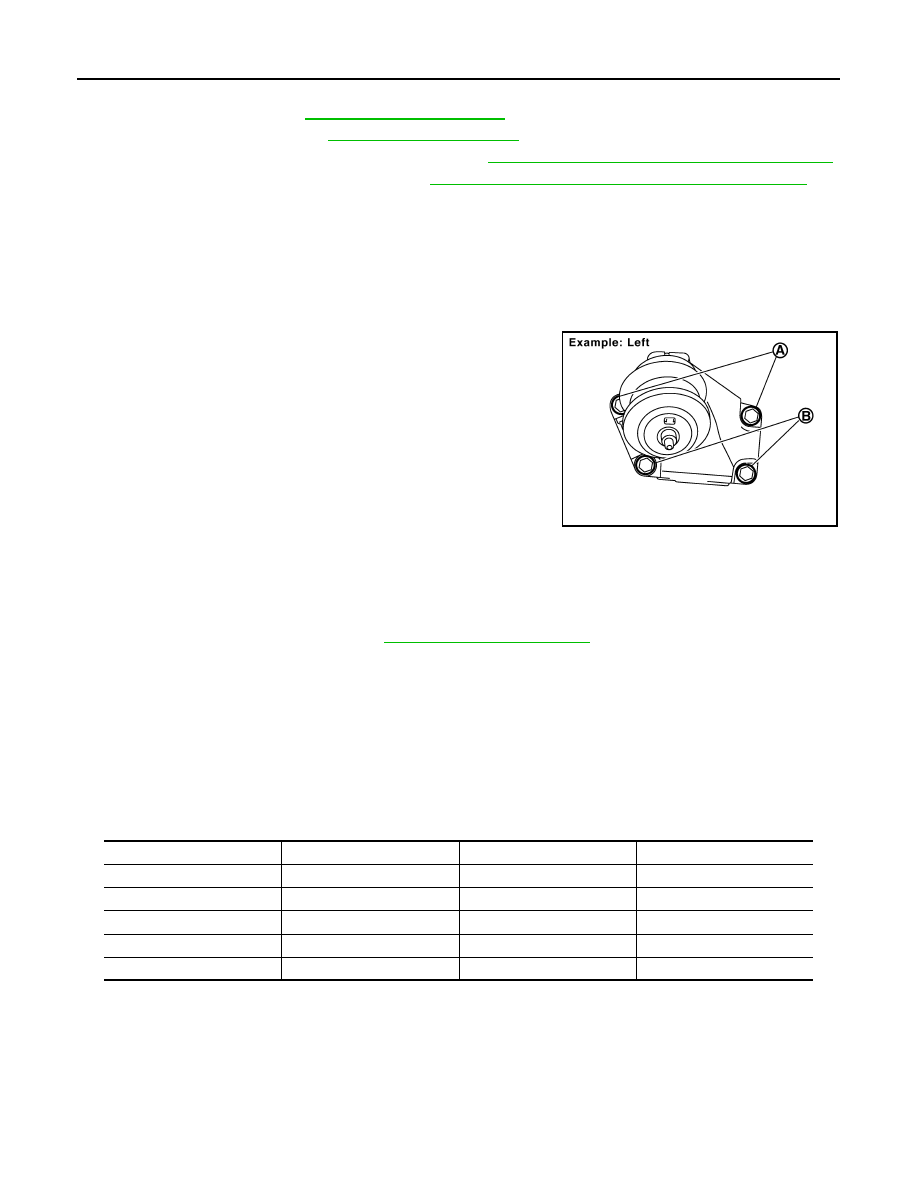
• When installing engine mounting brackets (RH and LH) on cylinder
block, tighten two upper bolts (shown as “A” in the figure) first.
Then tighten two lower bolts (shown as “B” in the figure).
INSPECTION AFTER INSTALLATION
Inspection for Leaks
The followings are procedures for checking fluids leak, lubricates leak and exhaust gases leak.
• Before starting engine, check oil/fluid levels including engine coolant and engine oil. If less than required
quantity, fill to the specified level. Refer to
.
• Use procedure below to check for fuel leakage.
- Turn ignition switch “ON” (with engine stopped). With fuel pressure applied to fuel piping, check for fuel leak-
age at connection points.
- Start engine. With engine speed increased, check again for fuel leakage at connection points.
• Run engine to check for unusual noise and vibration.
• Warm up engine thoroughly to make sure there is no leakage of fuel, exhaust gases, or any oil/fluids includ-
ing engine oil and engine coolant.
• Bleed air from lines and hoses of applicable lines, such as in cooling system.
• After cooling down engine, again check oil/fluid levels including engine oil and engine coolant. Refill to the
specified level, if necessary.
Summary of the inspection items:
*: Transmission/transaxle/CVT fluid. power steering fluid, brake fluid, etc.
PBIC2365E
Items
Before starting engine
Engine running
After engine stopped
Engine coolant
Level
Leakage
Level
Engine oil
Level
Leakage
Level
Other oils and fluid*
Level
Leakage
Level
Fuel
Leakage
Leakage
Leakage
Exhaust gases
—
Leakage
—
Нет комментариевНе стесняйтесь поделиться с нами вашим ценным мнением.
Текст