Infiniti FX35 / FX45. Manual — part 273
CO-22
< SERVICE INFORMATION >
[VQ35DE]
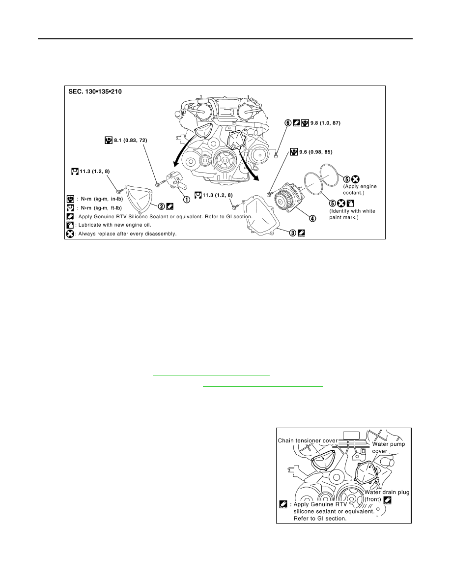
WATER PUMP
WATER PUMP
Component
INFOID:0000000001325856
Removal and Installation
INFOID:0000000001325857
CAUTION:
• When removing water pump assembly, be careful not to get engine coolant on drive belts.
• Water pump cannot be disassembled and should be replaced as a unit.
• After installing water pump, connect hose and clamp securely, then check for leaks using the radia-
tor cap tester (commercial service tool) and the radiator cap tester adapter (commercial service
tool).
REMOVAL
1.
Remove front engine undercover with power tool.
2.
Remove drive belts. Refer to
EM-15, "Removal and Installation"
3.
Drain engine coolant from radiator. Refer to
CO-10, "Changing Engine Coolant"
.
CAUTION:
• Perform this step when the engine is cold.
• Do not spill engine coolant on drive belts.
4.
Remove air duct (inlet), power duct and air cleaner case assembly. Refer to
5.
Remove water drain plug (front) on water pump side of cylinder
block to drain engine coolant from engine inside.
6.
Remove chain tensioner cover and water pump cover from front timing chain case.
• Use the seal cutter [SST: KV10111100 (J37228)] to cut liquid gasket for removal.
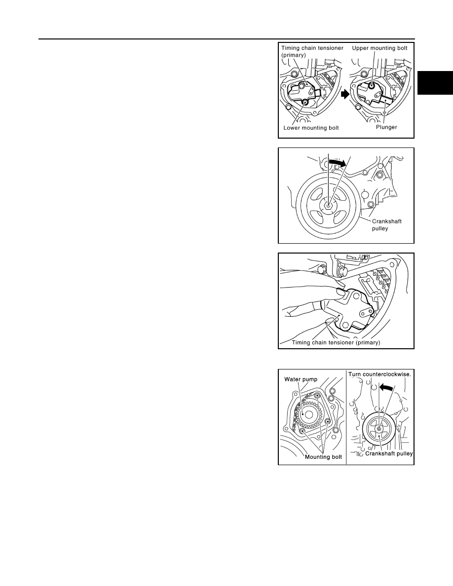
7.
Remove timing chain tensioner (primary) as follows:
1.
Timing chain tensioner (primary)
2.
Chain tensioner cover
3.
Water pump cover
4.
Water pump
5.
O-rings
6.
Water drain plug (front)
SBIA0482E
PBIC2662E
WATER PUMP
CO-23
< SERVICE INFORMATION >
[VQ35DE]
C
D
E
F
G
H
I
J
K
L
M
A
CO
N
P
O
a.
Remove lower mounting bolt.
CAUTION:
Be careful not to drop mounting bolt inside timing chain
case.
b.
Loosen upper mounting bolt slowly, and then turn chain ten-
sioner (primary) on the mounting bolt so that plunger is fully
expanded.
NOTE:
Even if plunger is fully expanded, it is not dropped from the body
of timing chain tensioner (primary).
c.
Turn crankshaft pulley clockwise so that timing chain on the tim-
ing chain tensioner (primary) side is loose.
d.
Remove upper mounting bolt, and then remove timing chain ten-
sioner (primary).
CAUTION:
Be careful not to drop mounting bolt inside timing chain
case.
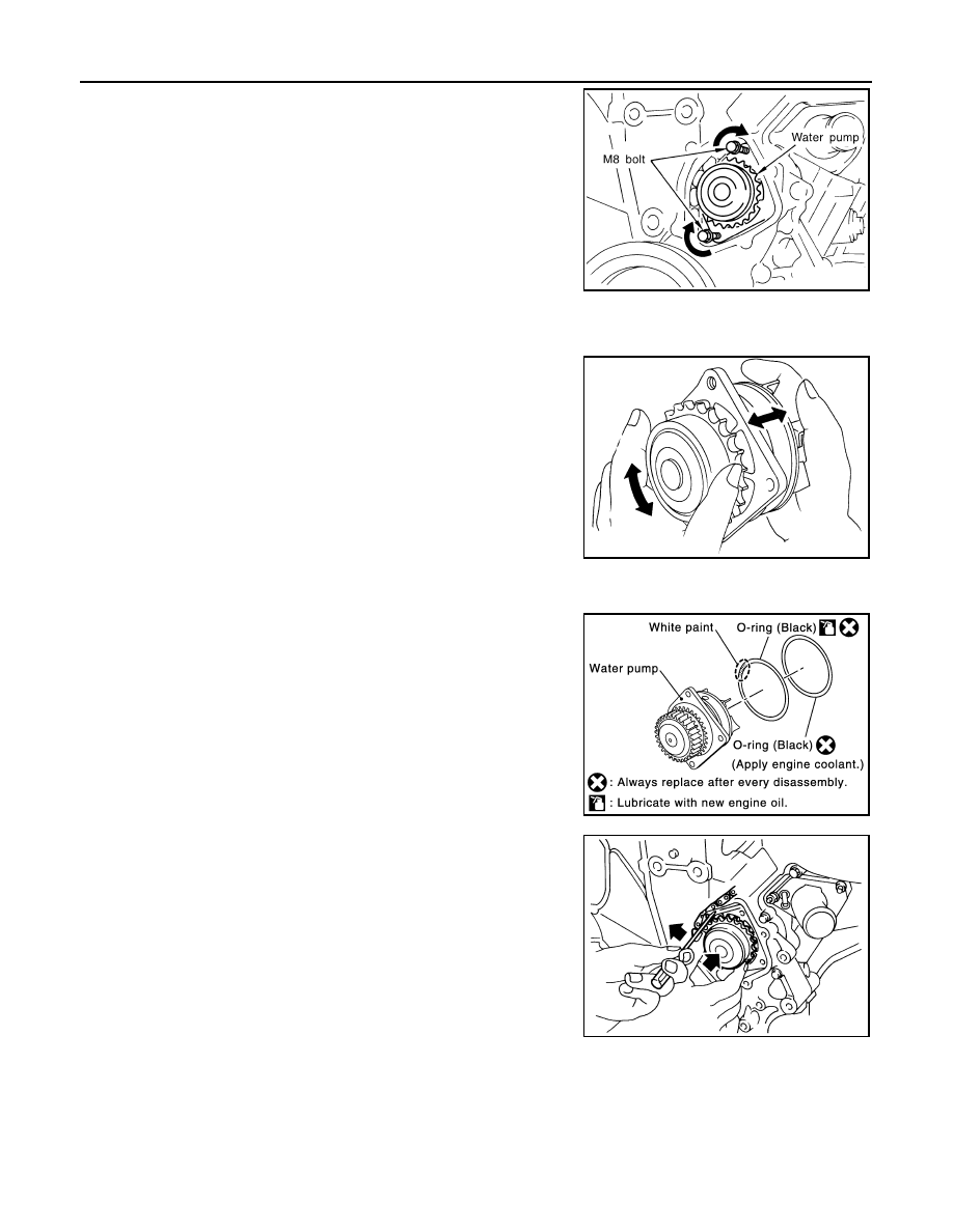
8.
Remove water pump as follows:
a.
Remove three water pump mounting bolts. Secure a gap
between water pump gear and timing chain, by turning crank-
shaft pulley counterclockwise until timing chain looseness on
water pump sprocket becomes maximum.
PBIC3575E
PBIC4820E
PBIC3576E
PBIC1193E
CO-24
< SERVICE INFORMATION >
[VQ35DE]
WATER PUMP
b.
Screw M8 bolts [pitch: 1.25 mm (0.0492 in) length: approx. 50
mm (1.97 in)] into water pumps upper and lower mounting bolt
holes until they reach timing chain case. Then, alternately
tighten each bolt for a half turn, and pull out water pump.
CAUTION:
• Pull straight out while preventing vane from contacting
socket in installation area.
• Remove water pump without causing sprocket to contact
timing chain.
c.
Remove M8 bolts and O-rings from water pump.
CAUTION:
Do not disassemble water pump.
INSPECTION AFTER REMOVAL
• Check for badly rusted or corroded water pump body assembly.
• Check for rough operation due to excessive end play.
• If anything is found, replace water pump.
INSTALLATION
1.
Install new O-rings to water pump.
• Apply engine oil and engine coolant to O-rings as shown in the
figure.
• Locate O-ring with white paint mark to engine front side.
2.
Install water pump.
CAUTION:
Do not allow cylinder block to nip O-rings when installing
water pump.
• Make sure timing chain and water pump sprocket are
engaged.
• Insert water pump by tightening mounting bolts alternately and
evenly.
3.
Install timing chain tensioner (primary) as follows:
JLC357B
SLC943A
PBIC1397E
PBIC1058E
WATER PUMP
CO-25
< SERVICE INFORMATION >
[VQ35DE]
C
D
E
F
G
H
I
J
K
L
M
A
CO
N
P
O
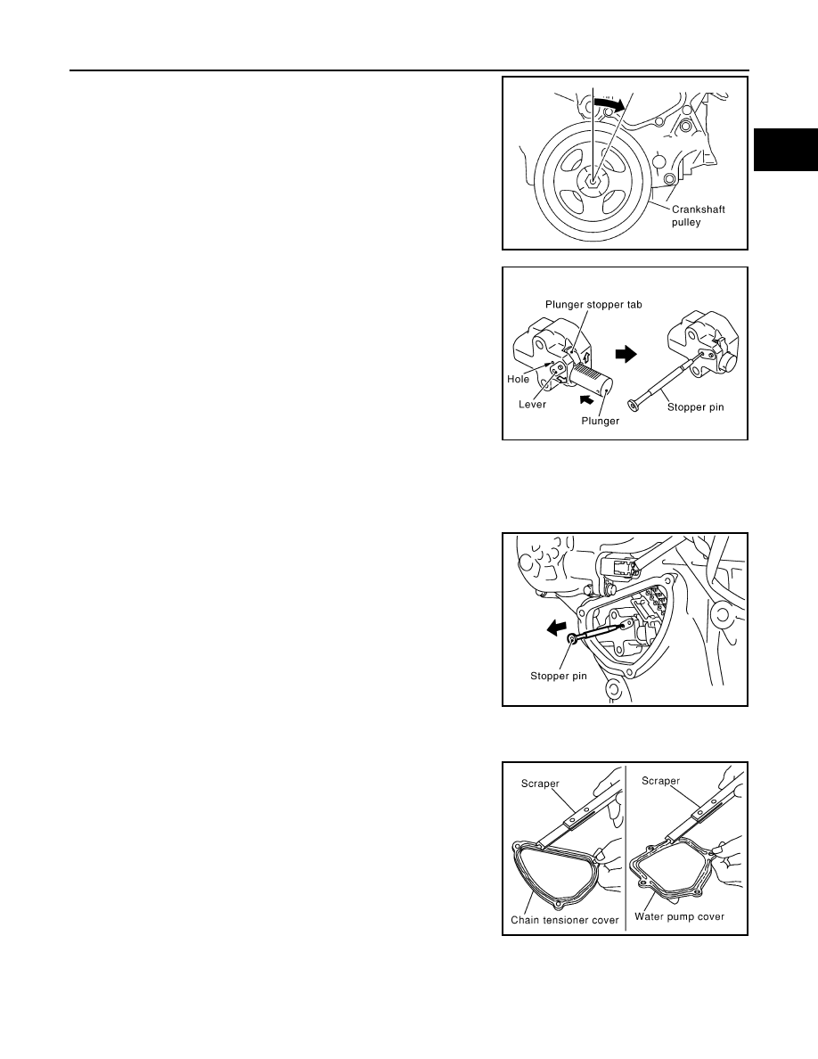
a.
Turn crankshaft pulley clockwise so that timing chain on the tim-
ing chain tensioner (primary) side is loose.
b.
Pull plunger stopper tab up (or turn lever downward) so as to
remove plunger stopper tab from the ratchet of plunger.
NOTE:
Plunger stopper tab and lever are synchronized.
c.
Push plunger into the inside of tensioner body.
d.
Hold plunger in the fully compressed position by engaging
plunger stopper tab with the tip of ratchet.
e.
To secure lever, insert stopper pin through hole of lever into ten-
sioner body hole.
• The lever parts and the tab are synchronized. Therefore, the
plunger will be secured under this condition.
NOTE:
Figure shows the example of 1.2 mm (0.047 in) diameter thin screwdriver being used as the stopper pin.
f.
Install timing chain tensioner (primary).
• Remove dust and foreign material completely from backside of timing chain tensioner (primary) and
from installation area of rear timing chain case.
g.
Remove stopper pin.
h.
Make sure again that timing chain and water pump sprocket are engaged.
4.
Install chain tensioner cover and water pump cover as follows:
a.
Before installing, remove all traces of old liquid gasket from mat-
ing surface of water pump cover and chain tensioner cover
using a scraper. Also remove traces of old liquid gasket from the
mating surface of front timing chain case.
PBIC4820E
PBIC3568E
PBIC3577E
SLC446B
Нет комментариевНе стесняйтесь поделиться с нами вашим ценным мнением.
Текст