Infiniti FX35 / FX45. Manual — part 274
CO-26
< SERVICE INFORMATION >
[VQ35DE]
WATER PUMP
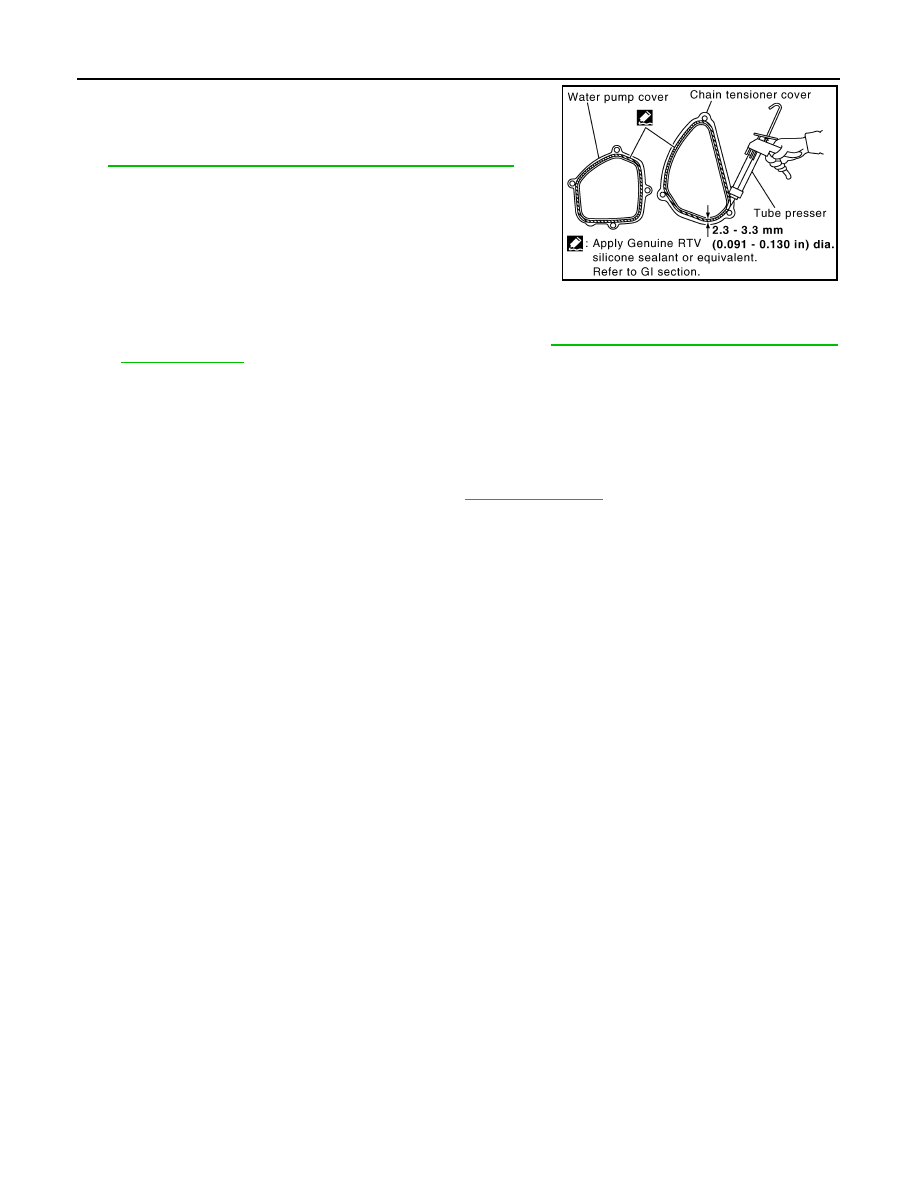
b.
Apply a continuous bead of liquid gasket with the tube presser
(commercial service tool) to mating surface of chain tensioner
cover and water pump cover.
Use Genuine RTV Silicone Sealant or equivalent. Refer to
GI-44, "Recommended Chemical Product and Sealant"
CAUTION:
Attaching should be done within 5 minutes after coating.
c.
Tighten mounting bolts.
5.
Install water drain plug (front) on water pump side of cylinder block.
• Apply liquid gasket to the thread of water drain plug (front).
Use Genuine RTV Silicone Sealant or equivalent. Refer to
GI-44, "Recommended Chemical Prod-
.
6.
Install in the reverse order of removal for remaining parts.
• After starting engine, let idle for three minutes, then rev engine up to 3,000 rpm under no load to
purge air from the high-pressure chamber of chain tensioner. Engine may produce a rattling
noise. This indicates that air still remains in the chamber and is not a matter of concern.
INSPECTION AFTER INSTALLATION
• Check for leaks of engine coolant using the radiator cap tester adapter (commercial service tool) and the
radiator cap tester (commercial service tool). Refer to
.
• Start and warm up the engine. Visually make sure that there is no leaks of engine coolant.
PBIC2663E
WATER INLET AND THERMOSTAT ASSEMBLY
CO-27
< SERVICE INFORMATION >
[VQ35DE]
C
D
E
F
G
H
I
J
K
L
M
A
CO
N
P
O
WATER INLET AND THERMOSTAT ASSEMBLY
Component
INFOID:0000000001325858
• Refer to
Removal and Installation
INFOID:0000000001325859
REMOVAL
1.
Remove front engine undercover using power tool.
2.
Drain engine coolant from radiator drain plug at the bottom of radiator, and from water drain plug at the
front of cylinder block. Refer to
CO-10, "Changing Engine Coolant"
.
CAUTION:
• Perform this step when the engine is cold.
• Do not spill engine coolant on drive belts.
3.
Remove air duct (inlet). Refer to
.
4.
Disconnect radiator hose (lower) and oil cooler water hose from water inlet and thermostat assembly.
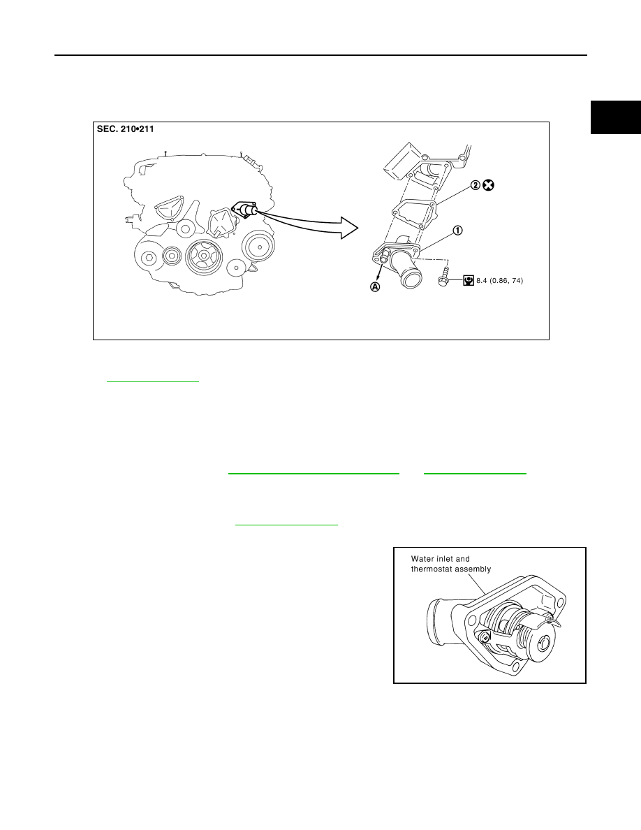
5.
Remove water inlet and thermostat assembly.
CAUTION:
Do not disassemble water inlet and thermostat assembly.
Replace them as a unit, if necessary.
INSPECTION AFTER REMOVAL
1.
Check valve seating condition at ordinary room temperatures. It should seat tightly.
1.
Water inlet and thermostat assembly 2.
Gasket
PBIC5002E
SLC962AB
CO-28
< SERVICE INFORMATION >
[VQ35DE]
WATER INLET AND THERMOSTAT ASSEMBLY
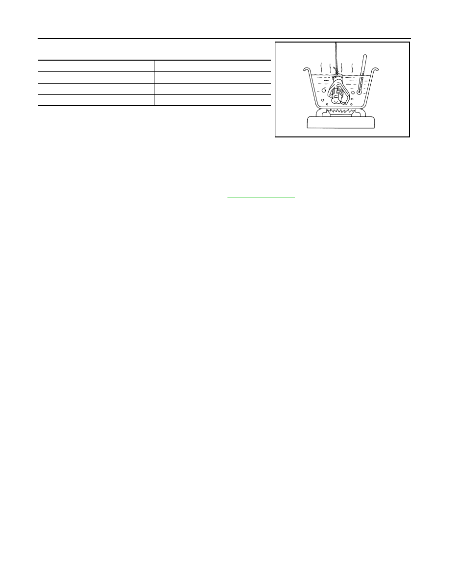
2.
Check valve operation.
• If the malfunctioning condition, when valve seating at ordinary
room temperature, or measured values are out of the standard,
replace water inlet and thermostat assembly.
INSTALLATION
Note the following, and install in the reverse order of removal.
• Be careful not to spill engine coolant over engine room. Use rag to absorb engine coolant.
INSPECTION AFTER INSTALLATION
• Check for leaks of engine coolant using the radiator cap tester adapter (commercial service tool) and the
radiator cap tester (commercial service tool). Refer to
.
• Start and warm up the engine. Visually make sure that there is no leaks of engine coolant.
Thermostat
Valve opening temperature
76 - 79
°
C (169 - 174
°
F)
Maximum valve lift
8.6 mm/90
°
C (0.339 in/194
°
F)
Valve closing temperature
71
°
C (160
°
F)
SLC949A

WATER OUTLET AND WATER PIPING
CO-29
< SERVICE INFORMATION >
[VQ35DE]
C
D
E
F
G
H
I
J
K
L
M
A
CO
N
P
O
WATER OUTLET AND WATER PIPING
Component
INFOID:0000000001325860
Removal and Installation
INFOID:0000000001325861
REMOVAL
1.
Remove front engine undercover with power tool.
2.
Drain engine coolant from radiator drain plug at the bottom of radiator, and from water drain plug at the
front of cylinder block. Refer to
CO-10, "Changing Engine Coolant"
.
CAUTION:
• Perform this step when the engine is cold.
• Do not spill engine coolant on drive belts.
3.
Remove engine cover with power tool. Refer to
4.
Remove air duct (inlet), air duct and air cleaner case assembly. Refer to
5.
Remove radiator hose (upper) and heater hose.
6.
Remove the following parts, when remove water outlet.
• A/T fluid charging pipe: Refer to
AT-241, "Removal and Installation (2WD Models)"
• Intake manifold collectors (upper and lower). Refer to
.
• Rocker cover (right bank). Refer to
.
7.
Remove engine coolant temperature sensor as necessary.
CAUTION:
Be careful not to damage engine coolant temperature sensor.
8.
Remove water outlet, heater pipe, water bypass hoses and water pipe.
INSTALLATION
1.
Harness bracket
2.
Water hose
3.
Water bypass hose
4.
Engine coolant temperature sensor
5.
Gasket
6.
Water outlet
7.
Heater hose
8.
Water pipe
9.
Radiator hose (upper)
10. Heater pipe
11.
Washer
12.
O-ring
SBIA0484E
Нет комментариевНе стесняйтесь поделиться с нами вашим ценным мнением.
Текст