Infiniti FX35 / FX45. Manual — part 643
CAMSHAFT
EM-89
< SERVICE INFORMATION >
[VQ35DE]
C
D
E
F
G
H
I
J
K
L
M
A
EM
N
P
O
4.
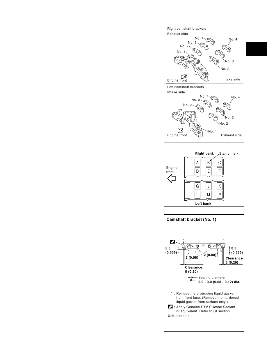
Install camshaft brackets.
• Remove foreign material completely from camshaft bracket
backside and from cylinder head installation face.
• Install camshaft bracket in original position and direction as
shown in figure.
• Install camshaft brackets (No. 2 to 4) aligning the stamp marks
as shown in the figure.
NOTE:
There are no identification marks indicating left and right for
camshaft bracket (No. 1).
• Apply liquid gasket to mating surface of camshaft bracket (No.
1) as shown on both right and left banks.
Use Genuine RTV Silicone Sealant or equivalent. Refer to
GI-44, "Recommended Chemical Product and Sealant"
.
PBIC2051E
PBIC2052E
PBIC2660E
EM-90
< SERVICE INFORMATION >
[VQ35DE]
CAMSHAFT
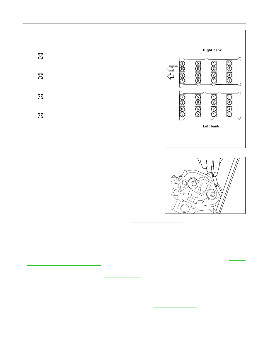
5.
Tighten camshaft bracket bolts in the following steps, in numeri-
cal order as shown.
a.
Tighten No. 7 to 10 in numerical order as shown.
b.
Tighten No. 1 to 6 in numerical order as shown.
c.
Tighten No. 1 to 10 in numerical order as shown.
d.
Tighten No. 1 to 10 in numerical order as shown.
CAUTION:
After tightening mounting bolts of camshaft brackets (No.
1), be sure to wipe off excessive liquid gasket from the
parts list below.
• Mating surface of rocker cover
• Mating surface of rear timing chain case
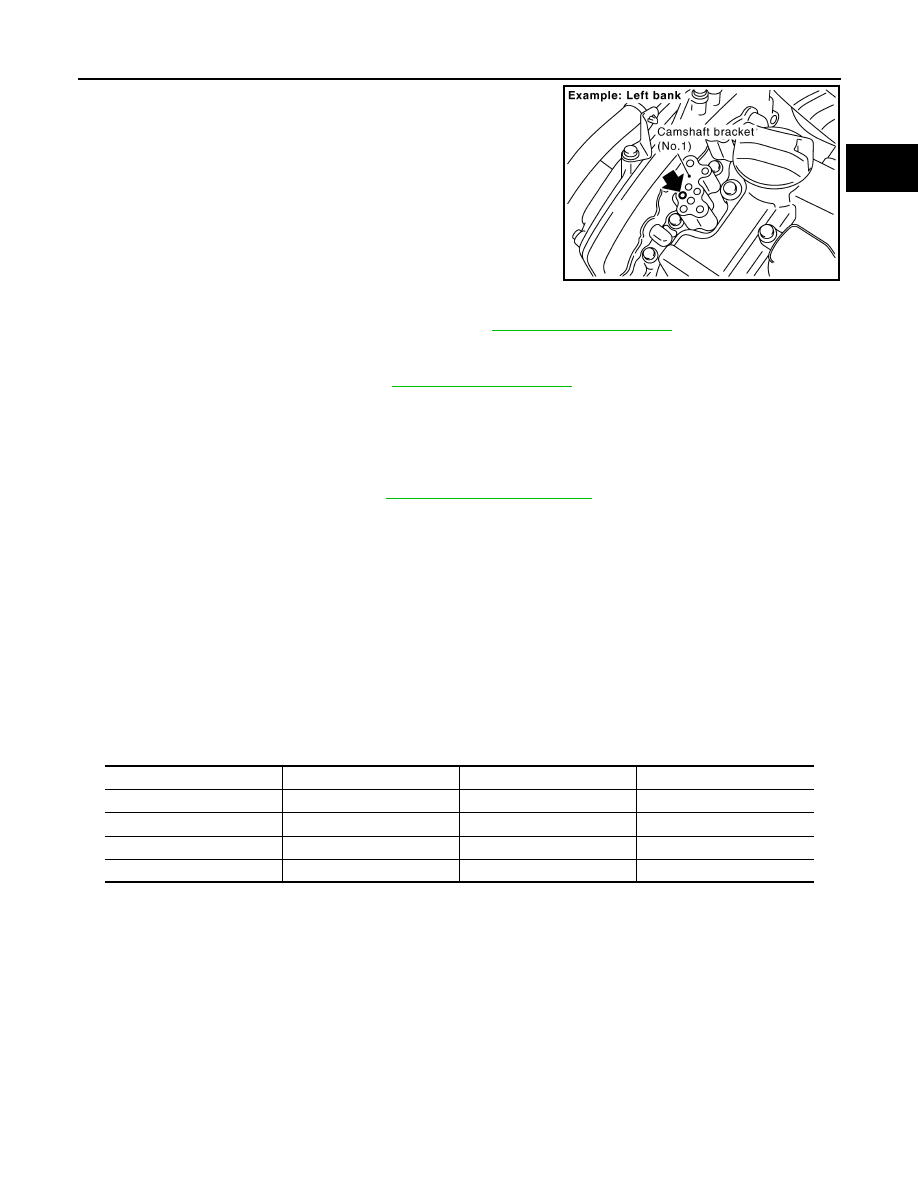
6.
Measure difference in levels between front end faces of cam-
shaft bracket (No. 1) and cylinder head.
• Measure two positions (both intake and exhaust side) for a
single bank.
• If the measured value is out of the standard, re-install cam-
shaft bracket (No. 1).
7.
Inspect and adjust the valve clearance. Refer to
.
8.
Install in the reverse order of removal after this step.
INSPECTION AFTER INSTALLATION
Inspection of Camshaft Sprocket (INT) Oil Groove
CAUTION:
• Perform this inspection only when DTC P0011 or P0021 are detected in self-diagnostic results of
CONSULT-III and it is directed according to inspection procedure of EC section. Refer to
"CONSULT-III Function (ENGINE)"
• Check when engine ins cold so as to prevent burns from any splashing engine oil.
1.
Check the engine oil level. Refer to
.
2.
Perform the following procedure so as to prevent the engine from being unintentionally started while
checking.
a.
Release fuel pressure. Refer to
b.
Disconnect ignition coil and injector harness connectors.
3.
Remove intake valve timing control solenoid valve. Refer to
.
: 1.96 N·m (0.20 kg-m, 1 ft-lb)
: 1.96 N·m (0.20 kg-m, 1 ft-lb)
: 5.88 N·m (0.60 kg-m, 4 ft-lb)
: 10.4 N·m (1.1 kg-m, 8 ft-lb)
PBIC2050E
Standard
: –0.14 to 0.14 mm (–0.006 to 0.006 in)
EMQ0044D
CAMSHAFT
EM-91
< SERVICE INFORMATION >
[VQ35DE]
C
D
E
F
G
H
I
J
K
L
M
A
EM
N
P
O
4.
Crank the engine, and then make sure that engine oil comes out
from camshaft bracket (No. 1) oil hole. End crank after checking.
WARNING:
Be careful not to touch rotating parts (drive belts, idler pul-
ley, and crankshaft pulley, etc.).
CAUTION:
Engine oil may squirt from intake valve timing control sole-
noid valve installation hole during cranking. Use a shop
cloth to prevent the engine components and the vehicle. Do
not allow engine oil to get on rubber components such as
drive belt or engine mount insulators. Immediately wipe off
any splashed engine oil.
• Clean oil groove between oil strainer and intake valve timing control solenoid valve if engine oil does not
come out from camshaft bracket (No. 1) oil hole. Refer to
5.
Remove components between intake valve timing control solenoid valve and camshaft sprocket (INT),
and then check each oil groove for clogging.
• Clean oil groove if necessary. Refer to
6.
After inspection, install removed parts.
Inspection for Leaks
The following are procedures for checking fluids leak, lubricates leak.
• Before starting engine, check oil/fluid levels including engine coolant and engine oil. If less than required
quantity, fill to the specified level. Refer to
.
• Use procedure below to check for fuel leakage.
- Turn ignition switch “ON” (with engine stopped). With fuel pressure applied to fuel piping, check for fuel leak-
age at connection points.
- Start engine. With engine speed increased, check again for fuel leakage at connection points.
• Run engine to check for unusual noise and vibration.
NOTE:
If hydraulic pressure inside timing chain tensioner drops after removal/installation, slack in the guide may
generate a pounding noise during and just after engine start. However, this is normal. Noise will stop after
hydraulic pressure rises.
• Warm up engine thoroughly to make sure there is no leakage of fuel, or any oil/fluids including engine oil and
engine coolant.
• Bleed air from lines and hoses of applicable lines, such as in cooling system.
• After cooling down engine, again check oil/fluid levels including engine oil and engine coolant. Refill to the
specified level, if necessary.
Summary of the inspection items:
* Transmission/transaxle/CVT fluid. power steering fluid, brake fluid, etc.
Valve Clearance
INFOID:0000000001325733
INSPECTION
Perform inspection as follows after removal, installation or replacement of camshaft or valve-related parts, or if
there is unusual engine conditions regarding valve clearance.
PBIC2869E
Items
Before starting engine
Engine running
After engine stopped
Engine coolant
Level
Leakage
Level
Engine oil
Level
Leakage
Level
Other oils and fluid*
Level
Leakage
Level
Fuel
Leakage
Leakage
Leakage
EM-92
< SERVICE INFORMATION >
[VQ35DE]
CAMSHAFT
In cases of removing/installing or replacing camshaft and valve-
related parts, or of unusual engine conditions due to changes in
valve clearance (found malfunctions during stating, idling or causing
noise), perform inspection as follows:
1.
Remove rocker covers (right and left bank). Refer to
2.
Measure the valve clearance as follows:
a.
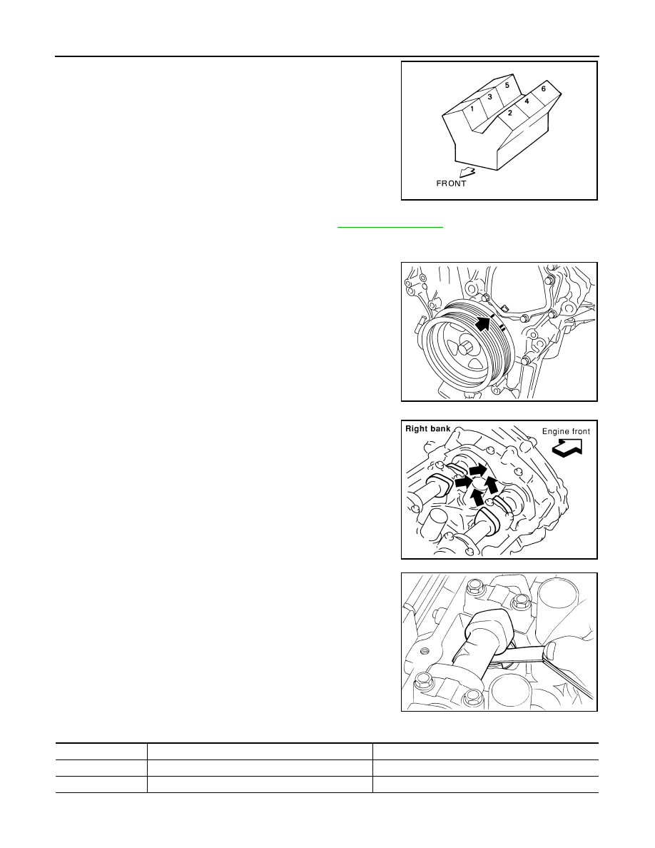
Set No. 1 cylinder at TDC of its compression stroke.
• Rotate crankshaft pulley clockwise to align timing mark
(grooved line without color) with timing indicator.
• Make sure that intake and exhaust cam nose on No. 1 cylinder
(engine front side of right bank) are located as shown in the
figure.
• If not, turn crankshaft one revolution (360 degrees) and align
as shown in the figure.
b.
Use a feeler gauge, measure the clearance between valve lifter
and camshaft.
Valve clearance:
Unit: mm (in)
*: Approximately 80
°
C (176
°
F)
SEM713A
KBIA1717J
SEM418G
SEM139D
Items
Cold
Hot * (reference data)
Intake
0.26 - 0.34 (0.010 - 0.013)
0.304 - 0.416 (0.012 - 0.016)
Exhaust
0.29 - 0.37 (0.011 - 0.015)
0.308 - 0.432 (0.012 - 0.017)
Нет комментариевНе стесняйтесь поделиться с нами вашим ценным мнением.
Текст