Infiniti FX35 / FX45. Manual — part 644
CAMSHAFT
EM-93
< SERVICE INFORMATION >
[VQ35DE]
C
D
E
F
G
H
I
J
K
L
M
A
EM
N
P
O
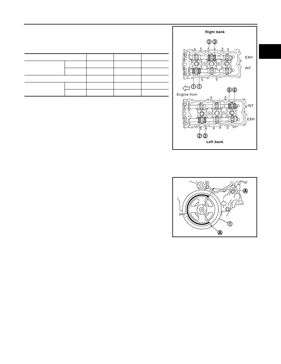
• By referring to the figure, measure the valve clearances at
locations marked “
×
” as shown in the table below (locations
indicated in the figure).
• No. 1 cylinder at compression TDC
c.
Rotate crankshaft by 240 degrees clockwise (when viewed from engine front) to align No. 3 cylinder at
TDC of its compression stroke.
NOTE:
• To align cylinder No. 3 with the compression top dead center,
place matching marks (A) on the crankshaft pulley (1) side and
on the cylinder block side at a point 240
°
counterclockwise
from the compression top dead center using the hex head of
the crankshaft pulley bolt as a guide.
Measuring position (right bank)
No. 1 CYL.
No. 3 CYL.
No. 5 CYL.
No. 1 cylinder at
compression TDC
EXH
×
INT
×
Measuring position (left bank)
No. 2 CYL.
No. 4 CYL.
No. 6 CYL.
No. 1 cylinder at
compression TDC
INT
×
EXH
×
PBIC2054E
PBIC4628J
EM-94
< SERVICE INFORMATION >
[VQ35DE]
CAMSHAFT
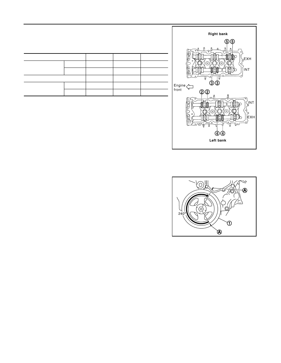
• By referring to the figure, measure the valve clearances at
locations marked “
×
” as shown in the table below (locations
indicated in the figure).
• No. 3 cylinder at compression TDC
d.
Rotate crankshaft by 240 degrees clockwise (when viewed from engine front) to align No. 5 cylinder at
TDC of compression stroke.
NOTE:
• To align cylinder No. 5 with the compression top dead center,
place matching marks (A) on the crankshaft pulley (1) side and
on the cylinder block side at a point 240
°
counterclockwise
from the compression top dead center using the hex head of
the crankshaft pulley bolt as a guide.
Measuring position (right bank)
No. 1 CYL.
No. 3 CYL.
No. 5 CYL.
No. 3 cylinder at
compression TDC
EXH
×
INT
×
Measuring position (left bank)
No. 2 CYL.
No. 4 CYL.
No. 6 CYL.
No. 3 cylinder at
compression TDC
INT
×
EXH
×
PBIC2055E
PBIC4628J
CAMSHAFT
EM-95
< SERVICE INFORMATION >
[VQ35DE]
C
D
E
F
G
H
I
J
K
L
M
A
EM
N
P
O
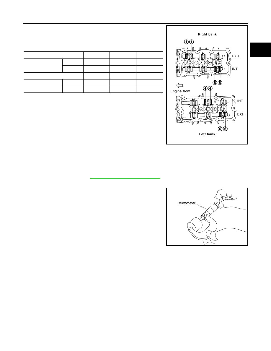
• By referring to the figure, measure the valve clearances at
locations marked “
×
” as shown in the table below (locations
indicated in the figure).
• No. 5 cylinder at compression TDC
3.
For measured value are out of the standard, perform adjustment. Refer to "ADJUSTMENT".
ADJUSTMENT
• Perform adjustment depending on selected head thickness of valve lifter.
1.
Measure the valve clearance. Refer to "INSPECTION".
2.
Remove camshaft. Refer to
EM-84, "Removal and Installation"
3.
Remove valve lifters at the locations that are out of the standard.
4.
Measure the center thickness of the removed valve lifters with a
micrometer.
5.
Use the equation below to calculate valve lifter thickness for replacement.
Measuring position (right bank)
No. 1 CYL.
No. 3 CYL.
No. 5 CYL.
No. 5 cylinder at
compression TDC
EXH
×
INT
×
Measuring position (left bank)
No. 2 CYL.
No. 4 CYL.
No. 6 CYL.
No. 5 cylinder at
compression TDC
INT
×
EXH
×
PBIC2056E
KBIA0057E
Valve lifter thickness calculation:
t = t
1
+ (C
1
– C
2
)
t
= Valve lifter thickness to be replaced
t
1
= Removed valve lifter thickness
C
1
= Measured valve clearance
C
2
= Standard valve clearance:
Intake
: 0.30 mm (0.012 in)*
Exhaust
: 0.33 mm (0.013 in)*
*: Approximately 20
°
C (68
°
F)
EM-96
< SERVICE INFORMATION >
[VQ35DE]
CAMSHAFT
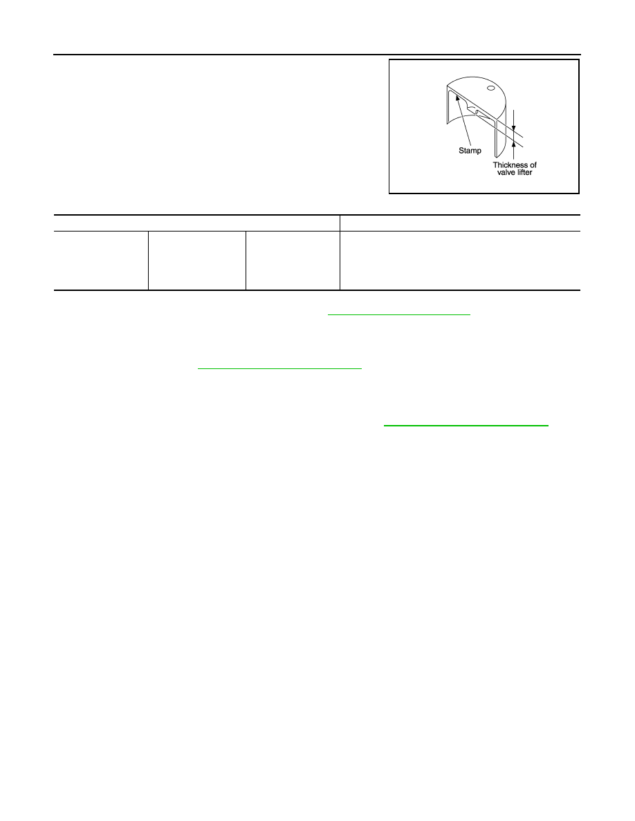
• Thickness of new valve lifter can be identified by stamp marks
on the reverse side (inside the cylinder).
Available thickness of valve lifter: 27 sizes with range 7.88 to 8.40 mm (0.3102 to 0.3307 in) in steps of 0.02
mm (0.0008 in) (when manufactured at factory). Refer to
.
CAUTION:
Install identification letter at the end, “U”, “R” and “V” at each of proper positions.
6.
Install selected valve lifter.
7.
Install camshaft. Refer to
EM-84, "Removal and Installation"
.
8.
Manually turn crankshaft pulley a few turns.
9.
Make sure that the valve clearances for cold engine are within the specifications by referring to the speci-
fied values. Refer to "INSPECTION".
10. Install all removal parts in the reverse order of removal. Refer to
EM-84, "Removal and Installation"
11. Warm up the engine, and check for unusual noise and vibration.
KBIA0119E
Stamp mark
Thickness
788U
790U
·
·
840U
788R
790R
·
·
840R
788V
790V
·
·
840V
7.88 mm
7.90 mm
·
·
8.40 mm
Нет комментариевНе стесняйтесь поделиться с нами вашим ценным мнением.
Текст