Infiniti FX35 / FX45. Manual — part 900
RSU-16
< SERVICE INFORMATION >
STABILIZER BAR
STABILIZER BAR
Removal and Installation
INFOID:0000000001327561
REMOVAL
1.
Remove tires from vehicle with power tool.
2.
Remove center muffler from vehicle. Refer to
.
3.
Remove fixing bolts and remove stabilizer connecting rod mount bracket from suspension arm with power
tool.
4.
Remove lower side fixing nut on stabilizer connecting rod and remove stabilizer connecting rod from stabi-
lizer bar with power tool.
5.
Remove fixing nuts on stabilizer clamps and remove stabilizer from vehicle with power tool.
INSPECTION AFTER REMOVAL
Check stabilizer bar, stabilizer bushings, stabilizer clamps, stabilizer connecting rod, stabilizer connecting rod
mounting bracket for any deformation, cracks or damage. Replace if necessary.
INSTALLATION
• Refer to
RSU-6, "Removal and Installation"
for tightening torque. Install in the reverse order of removal.
NOTE:
Refer to component parts location and do not reuse non-reusable parts.
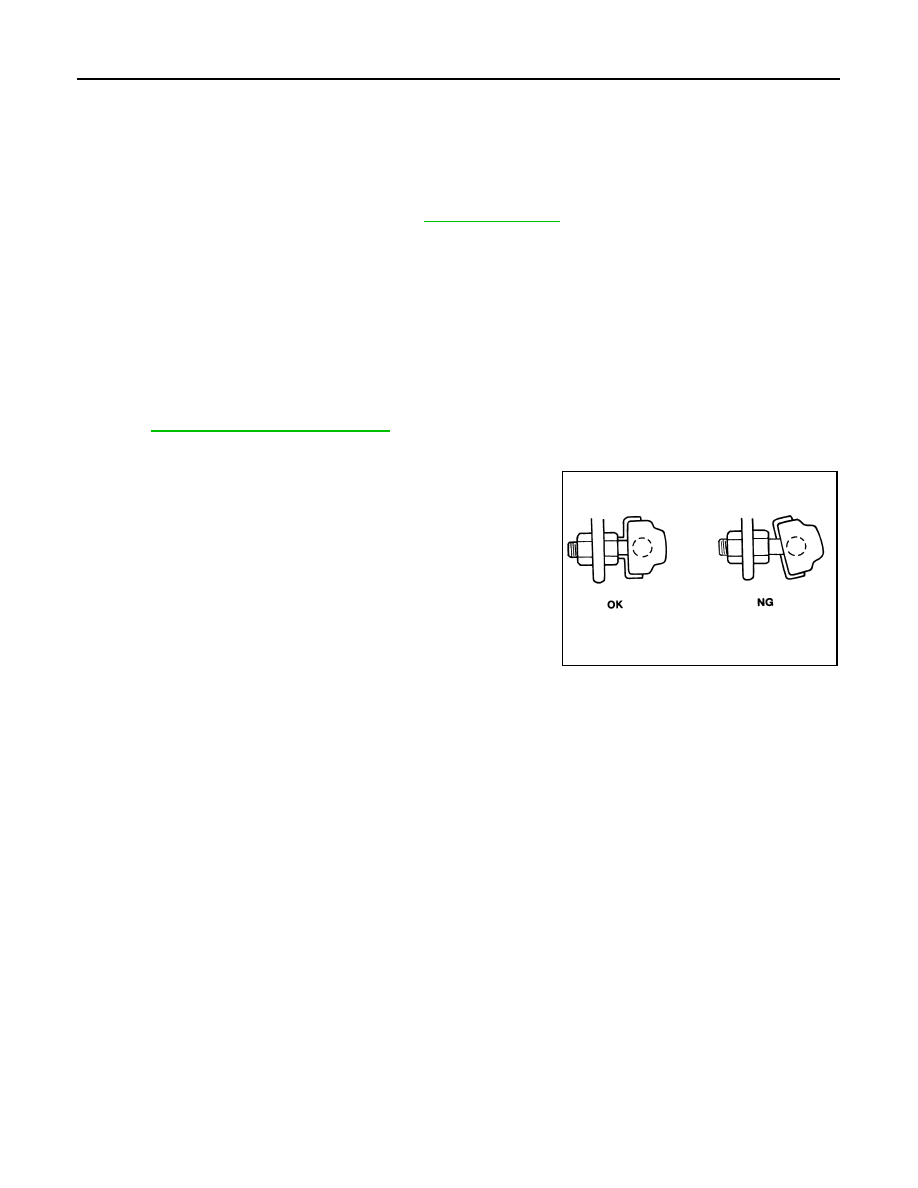
• Stabilizer bar uses pillow ball type connecting rod, position ball
joint with case on pillow ball head parallel to stabilizer bar.
• When the bushing and clamp are installed to stabilizer bar, position
the bushing and clamp inside of the side slip prevention clamp.
SFA449BB

REAR SUSPENSION MEMBER
RSU-17
< SERVICE INFORMATION >
C
D
F
G
H
I
J
K
L
M
A
B
RSU
N
O
P
REAR SUSPENSION MEMBER
Removal and Installation
INFOID:0000000001327562
REMOVAL
1.
Remove tires from vehicle with power tool.
2.
Remove brake caliper with power tool. Hang it in a place where it will not interfere with work. Refer to
.
NOTE:
Avoid depressing brake pedal while brake caliper is removed.
3.
Remove wheel sensor from rear final drive, then remove wheel sensor harness from rear suspension
member. Refer to
.
4.
Remove height sensor harness from rear suspension member (if equipped).
5.
Remove center muffler and main muffler. Refer to
.
6.
Remove stabilizer bar. Refer to
RSU-16, "Removal and Installation"
7.
Remove rear drive shaft. Refer to
.
8.
Remove propeller shaft. Refer to
9.
Remove rear final drive. Refer to
RFD-16, "Removal and Installation"
10. Separate attachments between parking brake cable and vehicle and rear suspension member. Refer to
11. Remove rear lower link and coil spring. Refer to
RSU-14, "Removal and Installation"
.
12. Remove fixing bolt in lower side of shock absorber with power tool.
13. Set jack under rear suspension member.
14. Remove fixing bolts and nuts of tunnel stay and member stay with power tool, then remove those parts
from vehicle and rear suspension member.
15. Remove fixing bolts and nuts of rear pin stay with power tool and then remove rear pin stay from vehicle
and rear suspension member.
16. Slowly lowering jack, then remove rear suspension member, suspension arm, radius rod, front lower link
and axle from vehicle as a unit.
17. Remove fixing bolts and nuts with power tool, then remove suspension arm, front lower link, and radius
rod from rear suspension member.
INSPECTION AFTER REMOVAL
Check rear suspension member for deformation, cracks, and other damage and replace if necessary.
INSTALLATION
• Refer to
RSU-6, "Removal and Installation"
, for tightening torque. Install in the reverse order of removal.
NOTE:
Refer to component parts location and do not reuse non-reusable parts.
• Perform final tightening of installation position of links (rubber bushing) under unladen conditions with tires
on level ground. Check wheel alignment. Refer to
RSU-5, "Wheel AlignmentInspection"
• After adjusting wheel alignment, adjust neutral position of steering angle sensor. Refer to
RSU-18
< SERVICE INFORMATION >
SERVICE DATA AND SPECIFICATIONS (SDS)
SERVICE DATA AND SPECIFICATIONS (SDS)
Wheel Alignment (Unladen*)
INFOID:0000000001327563
*: Fuel, engine coolant and lubricant are oil full. Spare tire, jack, hand tools and mats are in designated positions.
Ball Joint
INFOID:0000000001327564
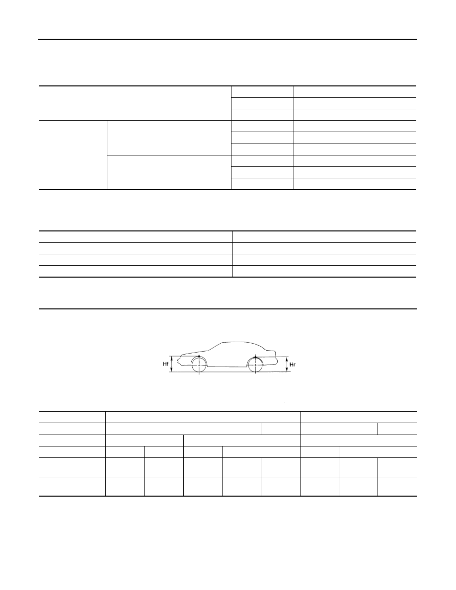
Wheelarch Height (Unladen*)
INFOID:0000000001327565
*: Fuel, engine coolant and lubricant are oil full. Spare tire, jack, hand tools and mats are in designated positions.
Camber
Degree minute (Decimal degree)
Minimum
–1
°
18
′
(–1.30
°
)
Nominal
–0
°
48
′
(–0.80
°
)
Maximum
–0
°
18
′
(–0.30
°
)
Total toe-in
Distance
Minimum
2.4 mm (0.09 in)
Nominal
4.7 mm (0.19 in)
Maximum
7.0 mm (0.28 in)
Angle (left wheel or right wheel)
Degree minute (Decimal degree)
Minimum
0
°
05
′
(0.08
°
)
Nominal
0
°
10
′
(0.17
°
)
Maximum
0
°
15
′
(0.25
°
)
Axial end play
0 mm (0 in)
Swing torque
0.5
−
3.4 N·m (0.06
−
0.34 kg-m, 5
−
30 in-lb)
Measurement on spring balance (cotter pinhole position)
9.7
−
66.0 N (0.98
−
6.7 kg, 2.18
−
14.8 lb)
Rotating torque
0.5
−
3.4 N·m (0.06
−
0.34 kg-m, 5
−
30 in-lb)
Destination
USA
Canada
Engine
VQ35DE
VK45DE
VQ35DE
VK45DE
Axle
2WD
AWD
AWD
Tire size
265/60R18
265/50R20
265/60R18
265/50R20
265/60R18
265/50R20
Front (Hf)
835 mm
(32.87 in)
834 mm
(32.83 in)
834 mm
(32.83 in)
833 mm
(32.80 in)
832 mm
(32.76 in)
834 mm
(32.83 in)
833 mm
(32.80 in)
832 mm
(32.76 in)
Rear (Hr)
822 mm
(32.36 in)
821 mm
(32.32 in)
829 mm
(32.64 in)
827 mm
(32.56 in)
825 mm
(32.48 in)
827 mm
(32.56 in)
826 mm
(32.52 in)
823 mm
(32.40 in)
SFA818A
SB-1
RESTRAINTS
C
D
E
F
G
I
J
K
L
M
SECTION
SB
A
B
SB
N
O
P
CONTENTS
SEAT BELTS
SERVICE INFORMATION . . . . . . .
PRECAUTIONS . . . . . . . . . . . . ...
Precaution for Seat Belt Service . . . . . . . ...
SEAT BELTS . . . . . . . . . . . . . ...
System Description . . . . . . . . . . . . ...
Removal and Installation of Front Seat Belt . . . .
Removal and Installation of Rear Seat Belt . . . ..
Seat Belt Inspection . . . . . . . . . . . . ..
LATCH (LOWER ANCHORS AND TETHER
FOR CHILDREN) SYSTEM . . . . . . . .
Removal and Installation . . . . . . . . . . ..
TOP TETHER STRAP CHILD RESTRAINT . .
Нет комментариевНе стесняйтесь поделиться с нами вашим ценным мнением.
Текст