Infiniti FX35 / FX45. Manual — part 899
RSU-12
< SERVICE INFORMATION >
SUSPENSION ARM
• If it is outside the specified range, replace suspension arm assembly.
INSTALLATION
• Refer to
RSU-6, "Removal and Installation"
for tightening torque. Install in the reverse order of removal.
NOTE:
Refer to component parts location and do not reuse non-reusable parts.
• Perform final tightening of rear suspension member installation position (rubber bushing) under unladen
conditions with tires on level ground. Check wheel alignment. Refer to
RSU-5, "Wheel AlignmentInspection"
.
• After adjusting wheel alignment, adjust neutral position of steering angle sensor. Refer to
RADIUS ROD
RSU-13
< SERVICE INFORMATION >
C
D
F
G
H
I
J
K
L
M
A
B
RSU
N
O
P
RADIUS ROD
Removal and Installation
INFOID:0000000001327558
REMOVAL
1.
Remove tires from vehicle with power tool.
2.
Set jack under rear lower link.
3.
Remove fixing bolt and nut in axle side of radius rod.
4.
Remove fixing bolt in rear suspension member side of radius rod with power tool, then remove radius rod
from vehicle.
INSPECTION AFTER REMOVAL
Check radius rod and bushing for any deformation, cracks, or damage. Replace if necessary.
INSTALLATION
• Refer to
RSU-6, "Removal and Installation"
for tightening torque. Install in the reverse order of removal.
NOTE:
Refer to component parts location and do not reuse non-reusable parts.
• Perform final tightening of rear suspension member and axle installation position (rubber bushing) under
unladen conditions with tires on level ground. Check wheel alignment. Refer to
• After adjusting wheel alignment, adjust neutral position of steering angle sensor. Refer to
RSU-14
< SERVICE INFORMATION >
FRONT LOWER LINK
FRONT LOWER LINK
Removal and Installation
INFOID:0000000001327559
REMOVAL
1.
Remove tires from vehicle with power tool.
2.
Set jack under rear lower link.
3.
Remove front lower link protector.
4.
Remove shock absorber assembly from vehicle. Refer to
RSU-9, "Removal and Installation"
.
5.
Remove fixing nut and bolt between front lower link and axle with power tool.
6.
Remove fixing nut and bolt between front lower link and rear suspension member with power tool.
7.
Remove front lower link from vehicle.
INSPECTION AFTER REMOVAL
Check front lower link and bushing for any deformation, crack, or damage. Replace if necessary.
INSTALLATION
• Refer to
RSU-6, "Removal and Installation"
for tightening torque. Install in the reverse order of removal.
NOTE:
Refer to component parts location and do not reuse non-reusable parts.
• Perform final tightening of rear suspension member and axle installation position (rubber bushing) under
unladen conditions with tires on level ground. Check wheel alignment. Refer to
.
• After adjusting wheel alignment, adjust neutral position of steering angle sensor. Refer to
REAR LOWER LINK & COIL SPRING
RSU-15
< SERVICE INFORMATION >
C
D
F
G
H
I
J
K
L
M
A
B
RSU
N
O
P
REAR LOWER LINK & COIL SPRING
Removal and Installation
INFOID:0000000001327560
REMOVAL
1.
Remove tire with power tool.
2.
Set jack under rear lower link.
3.
Loosen fixing bolt and nut between rear lower link and suspension member, and then remove fixing bolt
and nut between rear axle and rear lower link with power tool.
4.
Slowly lower jack, then remove upper seat, coil spring and rubber seat from rear lower link.
5.
Remove fixing bolt and nut between rear suspension member and rear lower link with power tool.
INSPECTION AFTER REMOVAL
• Check rear lower link, bushing and coil spring for deformation, cracks, and damage. Replace rear lower link
and coil spring if necessary.
INSTALLATION
• Refer to
RSU-6, "Removal and Installation"
for tightening torque. Install in the reverse order of removal.
CAUTION:
Refer to component parts location and do not reuse non-reusable parts.
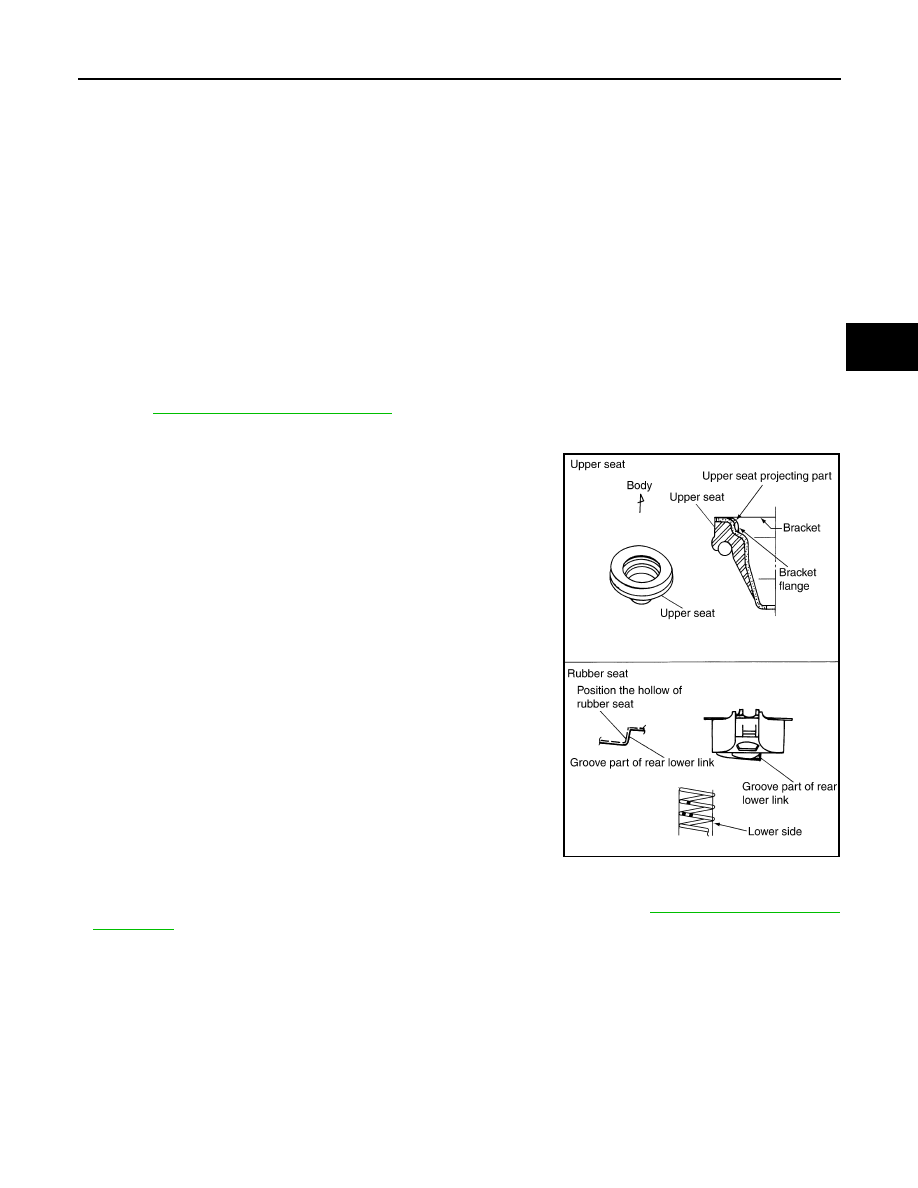
• Make sure upper seat is attached as shown in the figure.
NOTE:
Insert bracket tabs (3) and the inside protrusion on upper seat into
each other beforehand as shown in the figure.
• Match up rubber seat indentions and rear lower link grooves and
attach.
NOTE:
Make sure spring is not upside down. The top and bottom are indi-
cated by paint color.
• Perform final tightening of rear suspension member and axle installation position (rubber bushing) under
unladen conditions with tires on level ground. Check wheel alignment. Refer to
SEIA0229E
Нет комментариевНе стесняйтесь поделиться с нами вашим ценным мнением.
Текст